Table of Contents
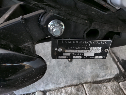
Identification
Battery
The scooter is powered by 5 lead-acid batteries each rated at  and
and  that are connected in series in order to achieve the total output of
  at
at  .
.
Perhaps the most noteworthy is the code 6-DZF-20 that can be used to search replacement batteries. Given the setup, it might be possible to convert the scooter from lead acid batteries to lithium or even LiFePo3.
The measurements are as follows:
- nominal voltage:
 ,
, - nominal capacity:
 ,
, - terminal type: M5,
- weight:
 ,
, - length: 181mm,
- width: 77mm,
- height: 167mm
Switching to Lithium Batteries
Due to the work involved, converting to lithium batteries is a separate project. However, just like any other scooter powered by lead-acid batteries, the scooter can easily be converted to use lithium batteries. Perhaps the only difficulty is the procurement of a battery with equivalent or more specifications as the lead acid battery.
Accessing the Front LCD Assembly
The LCD assembly consists in two plastic housings that are connected with each other, front and back, with screws to hold the assembly together and, regrettably, sometimes with some amount of glue. After removing the screws, the casing can be pulled on, with some attention given to the fact that the pieces might be glued together such that too much pressure might break the casing.
Furthermore, mind that the casing might be resting against the rear-view mirrors such that when trying to remove the case, the assembly might get stuck, needing some wiggling till the front casing can be taken off.
Two wires connect the front plastic LCD casing to the rest of the assembly that are meant for the turn signals. The cables can be easily disconnected and the front casing removed, leaving only the back casing.
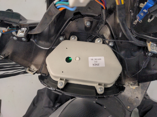
Removing the back casing, reveals a beige plastic box fixed with four screws into the plastic.
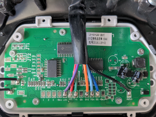
The four screws can be opened and the LCD PCB is revealed.
There are some interesting things to observe here:
- there is a JTAG connector running on the right side of the PCB, and incidentally,
- there are lines for
 (off the JTAG connector pin, or further to the right),
  (extreme left
 +12Vpad) and (
(V+andV-pads) allowing for further development
Controller
The controller reads ZWK060020A.
With the following features:
- anti-theft alarm (disconnected),
- honk
- two speeds (maybe three), allowing to commute between
 and
and  ,
, - can run at
 or
or 
Removing the Speed Limiter
For a moped or a vespa, unlike a blade scooter, it must be noted that there is no "implicit" speed limiter and that making the scooter allow faster speeds, is actually a matter of switching the electric scooter into a higher gear. Such scooters, when a producer is asked for a full-speed scooter, are delivered with a button on the handle that allows switching speeds; however when a limited-speed scooter is requested, the handlebar button is not even included and the "gear changing" connector is just wired to the first speed.
Ultimately and for elegance, after figuring out how the gears can be commuted, it is nice to maybe find a handlebar button and allow speeds to be switched, just like the full "unlimited" scooters.
The speed limiter typically corresponds to a three wire cable, usually colored with black, brown, dark blue and maybe with the following diagram as a representation:
Now, making a permanent contact between ground ("GND") and the pin on either side of the connection, results in either gear "1" or gear "2" being engaged, which, in turn, results in a maximal speed of  or
or  .
.
For this scooter, the speed limiter had the same three-wire coloring and a connector with two wires that connect to the pin on either side (not sure why that is necessary?) but as it turns out, just removing the connector makes the scooter switch to gear "2" thereby allowing faster speeds.
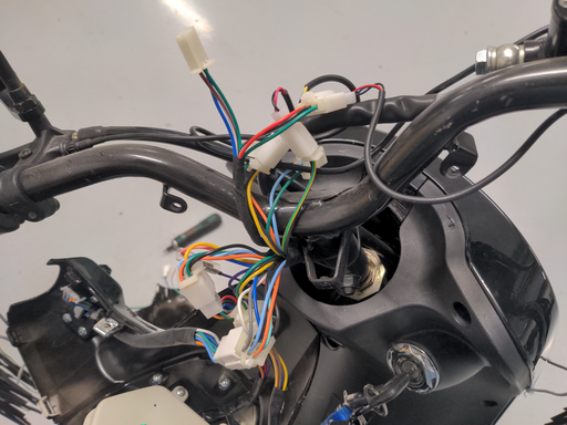
Another alternative is to not modify the controller itself, but rather go with the design of the scooter. Opening up the front LCD assembly, reveals three wires and a small dongle that loops back into the connector.
By simply flipping the connector around and with the scooter ignition on, the scooter seems to commute into the third gear.
| Gears | Switch |
|---|---|
| 1 | White/Blue to Green |
| 2 | Detached |
| 3 | White/Brown to Green |
Intuitively, even if the scooter is purchased with the speed limiter variant without gear shifting, the lower right part of the LCD assembly contains a slow where a switch would have existed that shifts gears such that the cable within the LCD assembly would have ended up connected to the gear switch. The switch required would be a rocker switch with three positions that runs through the possible configurations and shifts the gears of the scooter.
With that said, a followup project would be to purchase the rocker switch and then connect the cable as the scooter was supposed to be wired in its gear-switching variant.
USB Power Tap
Onboard devices (such as GPS, tire indicator, dashcam) are typically powered via an USB port such that it is necessary to pull a  line from somewhere that will charge the devices.
The scooter does have an USB port for charging devices, on the inner front part of the scooter, but it is a single USB A port and insufficient to charge all the onboard electronics.
The easiest is to locate and pull a  line from the LCD PCB and then use a rail splitter to distribute the
  to all onboard electronics, whether they are fixed on the left or right rear-view mirrors.
On the left side of the PCB there are two floating slots that apparently deliver  that can be tapped with a cable and then used to distribute the necessary power to charge the devices. Furthermore, it turns out that the PCB uses
  extensively throughout the circuit as can be observed by using a connectivity tester - this is good because it would indicate that the connector will be able to supply the necessary amperage to charge the onboard devices.
An even better job can be done by using a terminal block distributor bridge that can be mounted on the back of the plastic casing protecting the LCD display. Two wires are pulled from the same points on the PCB to the terminal block distributor and then USB cables are attached as necessary to draw  and recharge the various electronic devices.
Some hot melt glue is used to hold the cables down, however it is not a requirement and can be left out. The USB cable used is not an USB power cable but rather a complete USB cable with four wires because typically the complete USB cables have thicker individual wires on the inside allowing for more amperes to be drawn.
Restoring the Forward Fender and Other Plastic Damages
The scooter seems to be made out of some plastic and/or fiberglass compound that is pretty solid but it can happen on occasion for the plastic to chip such that repairs are needed. Unfortunately, using regular glue(s) does not work so well, mainly because the surface for a bit that got chipped off is not large enough for a proper weld; as well as using some instant epoxy glue such as "Super Glue" and other acrylics being very messy and error prone to disaster.
The typical solution to repairing such cases is to use a two-part compound putty where, in fact, the repair would consist in a restoration of the damaged parts, that will require both welding the broken part as well as reworking the part using paint primer and then paint. There are many options available, and the items used before have been "Magic Sculpt", now a similar item that is going to be used is Bison "EPOXY REPAIR", that seems to be similar to the putty used previously but is advertised to dry and set much sooner than the other.
The main technique using the two-part epoxy is to spread the compound on both pieces that are supposed to be glued together in order to increase the surface. The putty can be molded like mud around the cracks and also spread inside the cracks that are less obvious to fortify them. When the putty dries up, it turns into a hard cement-like compound that will be cleaned, sanded and then painted over to restore the original look of the piece to be repaired.
In this case, a large slice of the forward fender chipped off and needed to be reattached, such that some of the two part epoxy putty was added to the fault line, and then spread out to cover both sides of the fender being repaired. Of course, some of the preliminaries have been to use a large piece of sandpaper to clear out the area around the chip in order to allow for a better grip of the two-part epoxy putty.
One of the cool things about using two-part epoxy putty is that not only can it be used to remake the connections of chipped parts, but it can also be used to rebuild by literally sculpting back the original form. In this case, the fender had a series of chips where the bolt was supposed to go such that the whole section was recreated symmetrically to the same section on the other side.
The next step is to use sandpaper and remove the old black paint. For faster results, a Dremel can be used that will progressively scratch and chip the paint off the fender.
With the paint scratched off, paint primer can be used to give some ground to the repair before applying any color.
Blinker Signal
Apparently, motorcycles are not designed with an audible blinker signal such that it is easy to forget that the turn signal is on. While opening up the front LCD casing, it seems that the turn signal consists in just two wires per bulb that effectively intermittently switch the bulb on and off. It seems trivial that given the situation, a small electric buzzer an be attached to both sides (and only necessary at the front, where the LCD casing and the other controls are and where the driver's focus is) that will emit a noise whenever either signal is turned on.
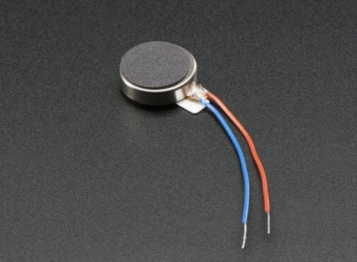
"Don't bikers have a helmet on so they won't be able to hear the buzzer?" and a good point that makes, so a better improvisation might be to purchase some cheap vibration motors such as the following.
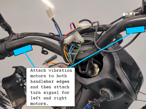
Then one of the motors can be added to the left handlebar and the other to the right handlebar as well as connected up to the turn signal such that whenever the left turn signal is on, the left handlebar part vibrates, and when the right turn signal is on, the right handlebar part vibrates. The rider will easily perceive the vibration due to the hands being placed on the handlebar and can still listen to whatever they need within the helmet.
Fortunately, the two vibration motors open up and can be extracted, such that they can be added to the handlebar directly and in direct contact in order to transfer the vibrations onto the connecting pipe.
Yay to a new invention! Now when the left-turn signal is engaged, the left part of the handlebar vibrates more than the right and it will be symmetrically the same for the right-turn signal. Implementation-wise, this is trivial due to vibration motors being rated by volts, so all it takes is to measure the voltage when the turn signal is on and then select a vibration motor that matches. Similarly, it might be that the motor vibrates too strongly, and in that case, a simple resistor or even a potentiometer can be placed in series in order to be able to tune the motor to an acceptable vibration level.
   either left or
  right turn signal

+                   +
|                   |
|                   |
|                   /
|                   \ R
|                   /
|                   +
|     +-------+     |
+-----+ Motor +-----+
    - +-------+ +
          M
Realization
The motors chosen have been very small 10mm diameter vibration motors because they produce enough vibration that an be transferred into the handlebars and do not consume too much battery.
The motors require about  but most adverts suggest that the voltage can be raised to about
  . In any case, they are simple enough to work with and can be mounted onto the handlebar on the left and right in order to induce some vibration into the hands of the driver.
Initially, there have been no measurements made to determine the voltage that powers the blinking lights but it is certain that they do not run at  such that the first step is to create a step-down that will reduce the voltage to
  .
.
In principle, the same type of wires can be used for both input and output from the buck converter, but in this case the input circuitry is fed through thicker wires and deliberately thin wires that match the default vibration motor wires are used to connect the motors.
Both motors are sold with some adhesive on the back, but it is clear that some more solid solution will b required when mounting the motors onto the handlebar. In any case, there is not much more to it than this; once the left blinker circuit is engaged, the left motor vibrates and then symmetrically the same takes place for the right.
For the contact, copyright, license, warranty and privacy terms for the usage of this website please see the contact, license, privacy, copyright.
