Table of Contents
ChangeLog
11 December 2018
- add the ability to read internal Roomba sensors and publish them to MQTT.
17 September 2018
- initial release of the Roomba-IoT software.
About
Not all Roombas support Wifi and, even with Wifi support, the Alexa functionality is rather limited and can only perform a fixed set of operations whilst the Roomba cleaning functions remains more or less the same across all models. A far better option to tap into Roomba deep magic is to embed some Wifi controller that would bridge Wifi networking to the serial Roomba interface thereby allowing the Roomba to be programmed using the Open Interface (OI) specification.
Similar projects have accomplished the forming by using a cheap ESP8266-based Wifi to serial port device. Unfortunately, micro ESP8266 wifi to serial port devices are usually limited to a single serial port interface and a wireless chip. Perhaps a better option would be to embed an entire Raspberry Pi into the Roomba thereby benefiting from the multitude of GPIO pins and countless Raspberry Pi extensions (sensors, audio cards, USB, etc...).
Requirements
- Raspberry Pi Zero W - The Raspberry Pi Zero W is acceptably small to fit inside the Roomba, has Bluetooth and Wifi integrated, benefits from an UART serial port and is a great choice to embed inside a Roomba.
- Step-down Buck Converter - The Roomba battery has a voltage of about
 whilst the Raspberry Pi Zero can be powered by
  . A voltage regulator will need to step down the
  from the Roomba battery and feed the Raspberry Pi.
Fitting the Raspberry Pi
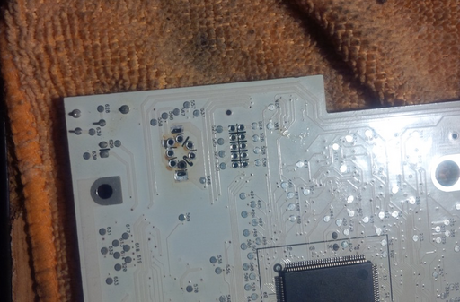
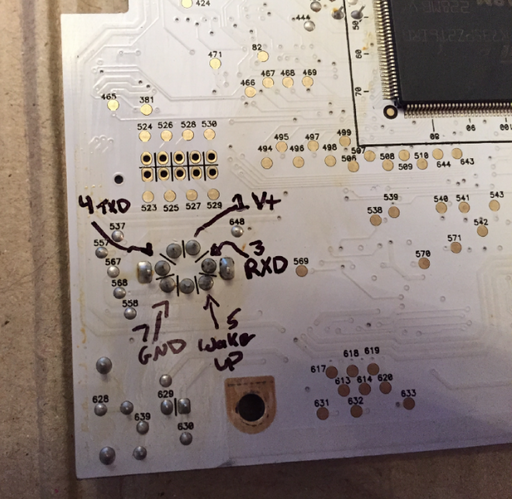
The Roomba has to be stripped down to the PCB in order to reveal the serial port leads. It is not necessary to remove the serial DIN port, but for a clean application it is advised. In order to do so, some soldering equipment is needed such as a desolder vacuum gun or desolder wick.
Removing the serial port DIN is not an easy task due to the multi-layer PCB but the result is a clean board with all connector pins exposed.
The Raspberry Pi Zero W fits very nicely in the upper side and underneath the PCB although the procedure is very difficult due to the large transistor heatsinks and the coil on the Roomba PCB. With a little bit of wiggling the Raspberry Pi Zero W can be made to fit such that the PCB can be securely screwed back with no visible sign of tampering.
As the images would indicate, leads are drawn from the Raspberry Pi connector using a ribbon Dupont cable to the serial port of the Roomba. The leads have been soldered onto the Raspberry Pi W instead of using Dupont headers in order to minimize space. Similarly, the Raspberry has been dressed with a large heat-shrink transparent plastic tube to insulate the board and other contacts from short-circuiting with the PCB and other leads.
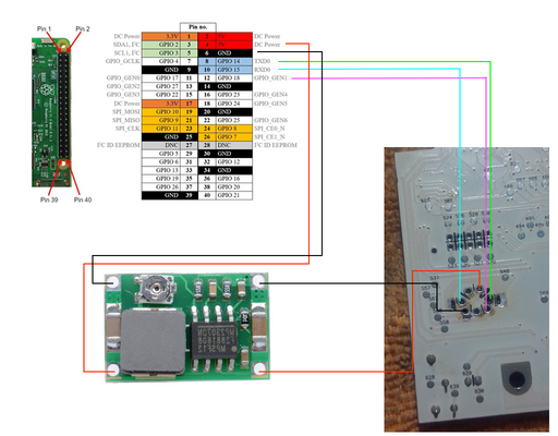
The correct wiring connects the Raspberry Pi UART serial to the Roomba serial TX and RX pins, the Roomba  output to the buck stepdown
  for the Raspberry Pi, plus an additional GPIO pin (18, in this case) to the Roomba DD Wake up pin.
Thus, the correct wiring for the entire setup is illustrated in the following sketch:
Operating System Setup and Testing
The Raspberry Pi is set up to automatically connect to the wireless network and UART serial is enabled for the TX and RX pins.
Using stty to set the serial parameters a quick test can be performed by issuing:
printf "\x80\x87" > /dev/serial0
where:
\x80\x87represents the start of a Roomba command\x80followed the command to clean\x87
IoT
Now that the Roomba is interfaced with, the Wizardry and Steamworks roomba-iot software package can be checked out in order to control the Roomba via MQTT and the Amazon Echo / Alexa.
First, some preliminary packages can be installed - assuming that the operating system is Linux and the distribution is Raspbian:
aptitude install nodejs npm subversion
followed by:
ln -sf /usr/bin/nodejs /usr/bin/node
and:
npm install -g npm
to update npm to a decent version.
Finally, the code can be checked out to any folder, say /srv:
cd /srv/
followed by:
svn co http://svn.grimore.org/roomba-iot
which should create a roomba-iot folder.
Inside the roomba-iot folder, the config.yml.default has to be renamed to config.yml and modified to point the software to an MQTT server and configure the topic to listen on.
The software can then be ran from the command line by issuing:
node main.js
which will connect to the MQTT server and listen on the topic specifed in config.yml. mosquitto_pub can then be used from a different machine to send a message to the specified topic that roomba-iot is listening on. For instance:
mosquitto_pub -h myhost.home -t roomba -m 'clean''
which will be picked up by roomba-iot making the Roomba start the cleaning program.
OpenHAB2 and Amazon Alexa
With an Amazon Alexa and OpenHAB2 a message can be sent to MQTT to turn on the Roomba. The OpenHAB2 setup includes two files, an items file placed at /etc/openhab2/items/roomba-iot.items:
/*************************************************************************/
/*                               Roomba-IoT                              *
/*************************************************************************/

Group Roomba_IoT "Roomba-IoT" <power>

Switch Roomba_IoT_Maintenance "Maintenance" <settings> (Roomba_IoT)

Switch Roomba_IoT_Switch "Roomba" (Roomba_IoT) ["Switchable"] {
	mqtt=">[mosquitto:roomba:command:*:JS(roomba-iot.js)]"
}
and a transformation file placed at /etc/openhab2/transform/roomba-iot.js:
(function(i){
    if(i === "OFF") {
        return 'dock';
    }
    if(i === "ON") {
        return 'clean';
    }
})(input)
Node-Red (with Amazon Alexa)
The roomba-iot project provides the capability to start, dock a Roomba but also the ability to read sensor data from the Roomba.
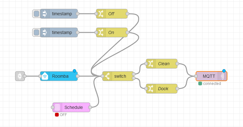
A Node-Red flow for toggling between start and dock states can be seen in the previous illustration where:
- the two
timestampnodes are injector nodes that allow starting, respectively docking the Roomba by clicking the button on the flow itself, - the
OffandOnnodes just set the payload tooff, respectivelyon, - the
switchnode will route the messages toroomba-iotcompatible commands, wherecleanrepresents the on state anddockthe off state, - the
MQTTnode will send the message to the MQTT broker thatroomba-iotsubscribes to.
One can also observe the Roomba node that is an Alexa Philips HUE compatible device that will allow turning the Roomba on by talking to Alexa and saying, "Alexa, turn Roomba on", respectively "Alexa, turn Roomba off" to make the Roomba dock. Optionally, a Schedule node can be added, setting the payload to on and off depending on the time of day in order to make the Roomba start and stop automatically based on a time schedule.
Reading sensors is made easy with roomba-iot since all sensor data will be posted to the MQTT broker specified in config.yml. By using an input MQTT node configured to output payloads from the topic configured for romba-iot and converting that data to JSON, an MQTT message will look like the following:
{
  "bump": {
    "right": 0,
    "left": 0
  },
  "wheeldrop": {
    "right": 0,
    "left": 0
  },
  "wall": false,
  "cliff": {
    "left": true,
    "front_left": true,
    "front_right": true,
    "right": true
  },
  "virtual_wall": false,
  "wheel_overcurrent": {
    "side_brush": 0,
    "main_brush": 0,
    "right_wheel": 0,
    "left_wheel": 0
  },
  "dirt_level": 0,
  "remote": 0,
  "buttons": {
    "clean": 0,
    "spot": 0,
    "dock": 0,
    "minute": 0,
    "hour": 0,
    "day": 0,
    "schedule": 0,
    "clock": 0
  },
  "distance": 0,
  "angle": 0,
  "battery": {
    "charging_state": 2,
    "voltage": 15725,
    "current": 938,
    "temp": 39,
    "charge": 1733,
    "capacity": 2696
  },
  "wall_signal": 0,
  "cliff_signal": {
    "left": 1,
    "front_left": 1,
    "front_right": 0,
    "right": 0
  },
  "charging_source": {
    "internal_charger": 0,
    "home_base": 2
  },
  "oi_mode": 1,
  "song": {
    "number": 0,
    "playing": 0
  },
  "stream_packets": 0,
  "last_requested_velocity": {
    "general": 0,
    "right": 0,
    "left": 0
  },
  "requested_radius": 0,
  "encoder": {
    "left": -24713,
    "right": 24189
  },
  "light_bumper": {
    "left": 0,
    "front_left": 0,
    "center_left": 0,
    "center_right": 0,
    "front_right": 0,
    "right": 0
  },
  "light_bump_signal": {
    "left": 2,
    "front_left": 0,
    "center_left": 0,
    "center_right": 0,
    "front_right": 0,
    "right": 0
  },
  "infrared": {
    "character": {
      "left": 0,
      "right": 0
    }
  },
  "motor_current": {
    "left": 0,
    "right": 0,
    "main_brush": 0,
    "side_brush": 0
  },
  "stasis": 0
}
where every single value can be picked out and then processed further.
For the contact, copyright, license, warranty and privacy terms for the usage of this website please see the contact, license, privacy, copyright.


