Table of Contents
About
The ATAS 120A is a motorized omnidirectional antenna, originally meant for the Yaesu series of HAM radios, and it is an antenna that is highly praised in the community due to its wide coverage of bands, working on all HAM bands up to VHF and UHF that are only supported using an additional counterpoise.
The working principle of the ATAS antenna, follows the wavelength equation where the wavelength varies with the length of the antenna, using a motor that can be engaged from the radio that will lengthen or shorten the antenna in order to match the desired frequency. In order to tuned the radio to a specific frequency, the following steps are carried out automatically by the radio or the antenna controller:
- the radio is set to emit a carrier, typically CW or AM of about
 power,
 - the SWR (signal reflection) meter is engaged in order to display the current SWR,
- the radio sends a signal to the antenna to shorten or lengthen the antenna whilst measuring the SWR,
- the radio stops tuning when it reaches an SWR that is under an SWR of
 or
or 
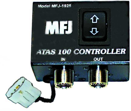
All of the former can also be performed manually by the operator by using the radio controls to lengthen or shorten the antenna whilst emitting a lower-powered signal. On the other hand, the ATAS antenna is self-standing equipment, and it is very plausible to use the ATAS antenna with radios other than Yaesu brand radios. To that end, the MFJ-1925 ATAS-120 antenna controller is powered by  via a molex connector and provides an up and down button to lengthen or shorten the antenna.
Regrettably, the MFJ-1925 controller is unbelievably expensive for what it does such that this documentation will provide the schematics and build instructions to create an ATAS controller for a tenth of the price of an MFJ-1925 controller.
Furthermore, because it is possible, the antenna controller that will be created will benefit from a remote control and will be able to control the ATAS at a distance instead of just providing an up and down button thereby making the controller easy to use as a portable device.
Controller Operation
The ATAS antenna controller is almost trivial for what it does and just follows the simple principle of operation:
- in order to extend the ATAS antenna, feed a voltage over
 through the antenna line,
 - to retract the ATAS antenna, feed a voltage of
 through the antenna line
Everything else that the ATAS antenna controller does is to protect the radio from the voltage that is supposed to be fed to the antenna via a capacitive bridge that is placed in front of the connector jack that leads to the radio.
Requirements
- 1 remote controller with two relays (can be just bought for a few bucks)
It is entirely possible to use an ESP8266 and some relays, perhaps a non-latching version of a low-power  featherwing relay, along with an RF module and a generic RF remote to build this module from scratch as well but it is not necessary and ultimately it does not bring anything new to the build.
L7805voltage regulator,- two
 capacitors (or
  ) for the voltage regulator,
 - three
 ceramic capacitors rated at
  to create a voltage blocking bridge for the voltage to not flow into the radio,
 - two
 resistors,
 - one
 resistor (a small surface-mounted potentiometer would be good as well for calibration),
 - an SPST micro-relay, with a a coil voltage ranging somewhere between
 and
and  ,
, - a PCB mounted jack to power the build with
 ,
, - a
 inductor / RF choke,
 - a basic diode that can sustain up to
 of current,
 - antenna jacks (PL),
- a mounting box,
- the usual building materials; PCB, soldering equipment, copper thread, etc.
Schematics
Given the very simple mode of operation ( for retract,
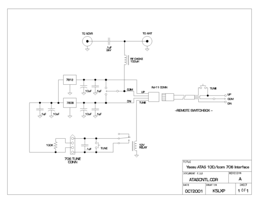
  to extend) there are numerous schematics that can be built. For example, K5LXP builds an ATAS controller with two voltage regulators
 L7812, that provides  to extend the antenna, respectively an
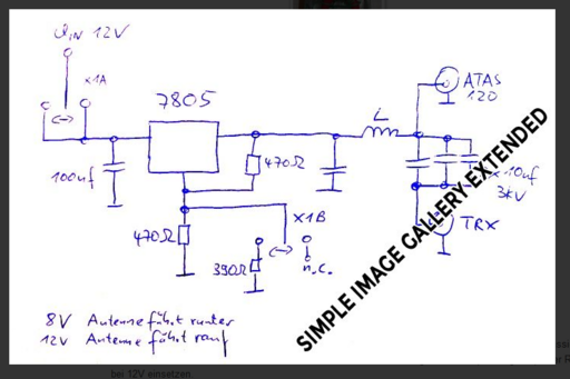
 L7808 that provides  to retract the antenna. There's a more interesting schematic, by DG1SFJ that uses a single voltage regulator which is neither better nor worse but somewhat cooler given the principle of minimization of circuitry.
The basic schematics provided by DG1SFJ are also very easy to realize, and are not much more than the schematic mentioned by the voltage regulator but with the extra addition of a feedback resistor that allows to control the output voltage of the voltage regulator by draining the voltage regulator using varied resistors. In fact, the lengthier task is to calibrate the voltage output by varying the resistors and ensuring that  , respectively
  can be generated selectively just by commuting between contacts. If that part is realized, then the remote control commuter with the relays can just be interposed and made to switch between voltages in order to extend or retract the ATAS.
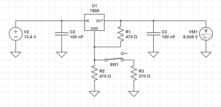
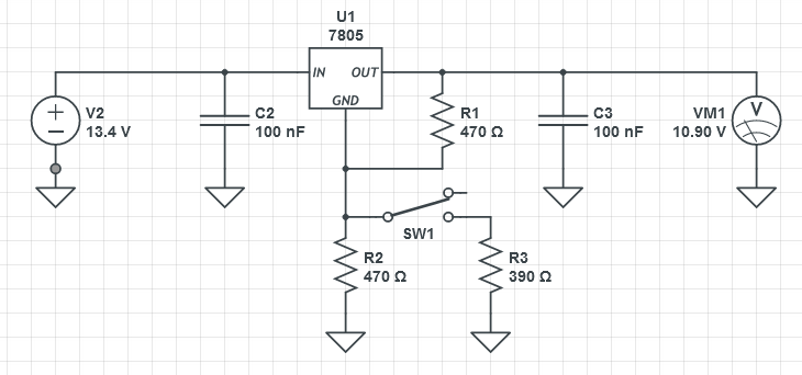
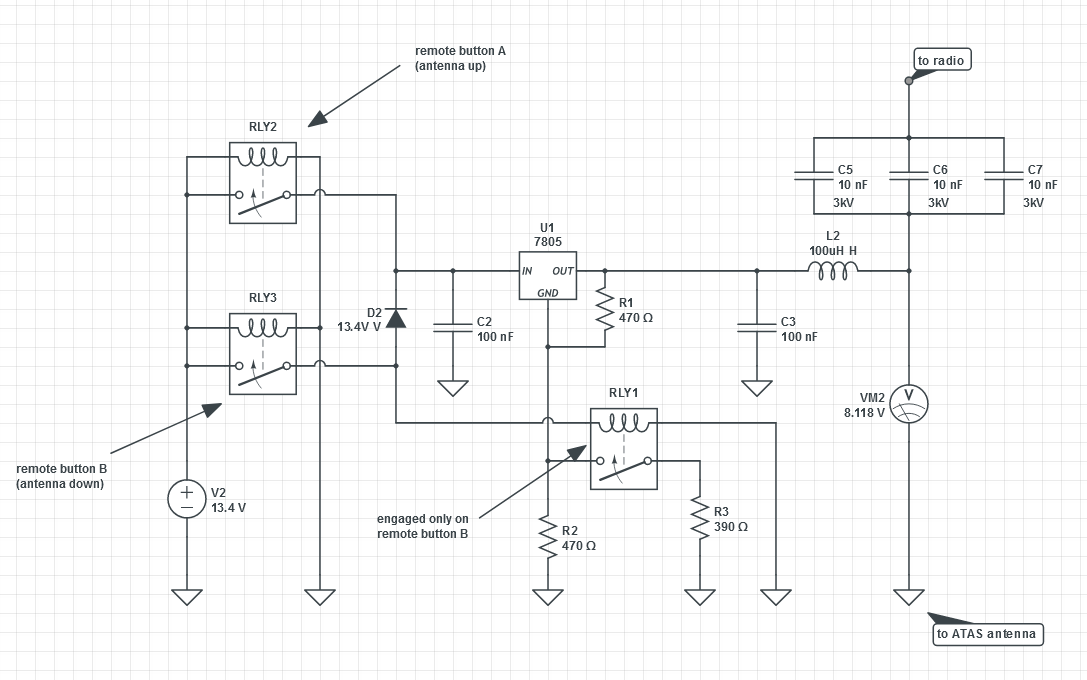
Using CircuitsLab, the schematic can be simulated in order to ensure the proper voltage output required by the antenna based on one single L7805,  voltage regulator.
The circuit is the recommended circuit for a voltage regulator, the capacitors C2 and C3 being added as recommended by the L7805 data sheet, and with a voltage source on one side and a voltmeter on the other side.
The addition of a feedback resistor R1 allows the voltage of the regulator to be surpassed and by commuting the drain through R2, respectively R2 and R3 via the SW switch, the voltage regulator is made to output  in order to retract the antenna, respectively
  to extend the antenna.
It is important to remember that the car battery voltage is nominally  and not the theoretical
  such that the schematics are calculated using
  instead. Even though the controller will not be used with car battery, one previous project involved modifying an HP server power supply to provide the necessary
  to a HAM radio, such that the voltage will indeed be set to
  instead of just
  .
.
When attempting to simulate the original circuit, the correct voltages were never obtained, and this is due to the notations that are wrong on the original schematic, namely that  are not necessary and the ATAS is in fact happy with any voltage over
  in order to extend the antenna.
For example, K5LXP presents a schematic with two voltage regulators L7812 and L7808, which is the most straightforward solution that takes care to downscale any voltage exactly to  , respectively
  .
.
The schematic has some issues, namely that linear voltage regulators with a constant voltage output typically need about  above their conversion value, such that the
 L7812 might have hard time providing  and that is even if the power from the battery is
  . Next, it just seems that two voltage regulators is overkill if the same can be achieved with just one single voltage regulator from the point of view of circuit minimization but on the other hand it is not that bad of an idea either considering that the voltage regulators used have a fixed constant output that will ensure the voltage output.
Another problem is that FG1SFJ will only power on the device when the antenna needs to be retracted or extended, such that the derived schematics mentioned earlier will have to be modified in order to ensure that power flows to the regulator only when the button on the remote controller is pressed. In fact, the provided schematic has two separate commuters, the top-most switch that engages to feed the circuit with  voltage, and the lower switch that couples the
  resistor in order to attain
  . This is where the additional micro-relay comes in for the derived and final schematic that, upon the need to retract the antenna, will both power the voltage regulator as well as coupling the
 R2 and R3 resistor to ground thereby attaining  . In effect, the remote control circuit and the relays will just power the voltage regulator with the down button having the additional effect of stepping down the voltage even further to retract the antenna.
The final circuit can then be sketched up as:
with the following mentions:
- the relays
RLY2andRLY3are the existing relays on the remote controller module and they are engaged intermittently whenever buttonAor buttonBis pressed on the remote control, buttonA(antenna up) engaging relayRL2and buttonB(antenna down) engaging relayRLY3, - the diode
D3is there to separate between the common that engages the
 L7805voltage regulator such that pressing buttonAwill not accidentlly engage the third relayRLY1that is responsible for dropping down the voltage to (otherwise both
 AandBbuttons on the remote would only generate ),
), - the relays,
RLY3,RLY2andRLY1, on the schematic have the following role:- both
RLY3andRLY2will power the voltage regulatorL7805in order to drop-down from ,
, RLY2, will just power the voltage regulator and will output for the antenna to go up,
RLY3, will power the voltage regulator and also additionally will power relayRLY1that will drop-down to in order to make the antenna retract,
- the capacitive bridge consisting of ceramic capacitors
C5,C6andC7are rated at and
and  each and are responsible for the generated current to not flow back into the radio when the antenna is operated, either retracted or extended
It is already observable that, given the current state of the circuit, the voltmeter VM2 reads  . This is due to all relays
 RLY2, RLY3 and RLY1 being coupled such that the circuit generates the required  to retract the antenna. If
 RLY3 were to be decoupled, RLY3 would additionally decouple RLY1 and assuming that RLY2 would be coupled, the necessary  would be generated in order to extend the antenna.
Limitations
One limitation is that the circuit is fully dependent on the input voltage that is supplied to the circuit. Supplying less than  might have unintended consequences with the more than likely outcome being that the circuit will only be able to retract the antenna.
As an example, a voltage of  being supplied to the circuit results in the "low" voltage generated by the regulator being
  which has the surprising effect of lowering the antenna instead of extending it.
While testing, if both extend and retract buttons on the remote have the effect of just lowering the antenna, at different speeds, then make sure to measure the input voltage because it just might be lower than the  nominal voltage.
Realization
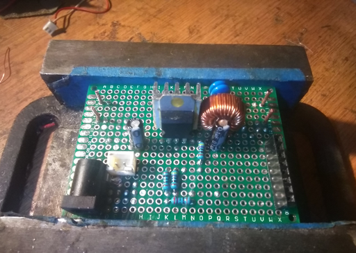
With the theory established, the circuit can now be built and the project realized. Iteratively, the circuit is built around the L7805 voltage regulator since it will be the centerpiece of the circuit with clear left-and-right separation of "before stepping down" and "after stepping down".
On the back, traces are built using thin copper wire to connect the individual components together.
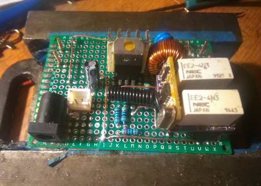
At some point it is decided to not solder the remote controller onto the PCB, but rather remove the provided wires on the remote controller and then add pins with a matching socket on the PCB such that the remote controller can be added and removed simply by plugging it onto the PCB.
The black  jack is mounted on the side, two pairs of copper struts protrude from the PCB to which the antenna sockets will be soldered, both going to the antenna on the right-side and then going to the radio transmitter on the left side of the PCB. Even though it is not necessary, a small JST connector (white) is added to the PCB from whencefrom
  can be drawn.
The PCB is then finalized with some "wild traces" drawn as copper wires from the bottom to the top and by sliding the copper wire between the various components in order to not extend the height of the PCB nor build too many bridges for the circuitry on the bottom part of the PCB.
As it can be observed, there are four resistors and this is due to not having the exact value  for the
  drop-down part of the circuit, such that two resistors in series are used instead to generate an approximate value that will be sufficiently good to retract the antenna.
Note that the capacitors used for the voltage regulator are polarized, but only incidentally so due to not wanting to use surface-mounted Tantalum capacitors. That is not a problem and the positive pole of the capacitor is connected to the pins of the voltage regulator. On the other side, the blue ceramic capacitors can be seen, along with the  inductor that form the voltage blocker in order to not damage the radio. The leads to and from the ATAS connector and the radio are realized out of a pure copper wire in order to maximize the connectivity between them. Even though the voltage regulator has a heatsink, a smaller heatsink is attached due to the fact that the voltage regulator is not expected to run for lengthier periods of time but will rather be engaged whenever either button is pressed on the remote control.
The final step is to find or create a matching case, preferably made out of aluminum in order to minimize RF noise radiated towards the exterior of the circuit. A metal project-box will suffice but it will have be tall enough to accommodate for the antenna connectors that tend to be pretty bulky. One issue that might be encountered is that the remote uses RF such that the pigtail antenna might have to be removed from the remote controller PCB and relocated somewhere on the outside of the project box metal case in order to avoid the Faraday cage effect. However, it is expected that the project will be operated fairly close up without too large of a distance between the remote control and the realized circuitry.
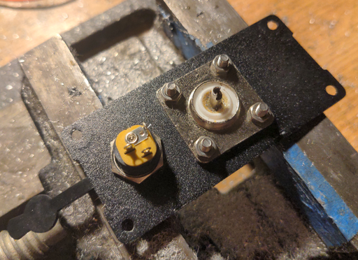
With the box delivered, it is time to fit in all the electronics in the box. Power is supplied via a standard 3.5mm power jack with a female part that can be mounted onto the sides of the box and connected to the PCB via a JST connector. In order to accomplish this, holes have been drilled in both ends of the box, something that was a more difficult task due to the box being made out of solid aluminum.
The PL259 antenna connectors are connected to the PCB using pure copper hard-wires and soldered onto each other in order to hopefully achieve a perfect contact.
With the box closed, the result does not look too spectacular yet a quick testing with the ATAS-120 shows that indeed, pressing the upper button marked "A" will make the antenna extend, conversely pressing the button marked "B" will make the antenna retract, exactly as planned.
Testing
Here are some testing protocols used to ensure that the ATAS-120 tuner functions correctly.
Connectivity
Connectivity was tested to ensure that the power jack is correctly routed to the correct sub-circuit on the PCB, ground being group, and the positive pole with the sub-circuit needing the positive pole. This was carried out from the sides of the box to the PCB by measuring the cable.
Power Flow
Three separate measurements have been carried out, with the circuit powered at  :
:
- on the end of the box that is connected to the antenna, using alligator clips, the potential was measured when the "A" button on the remote is pressed, indicating
 and then with the "B" button pressed on the remote, indicating
  ,
, - on the other end of the box, that connects to the radio, the potential was measured when pressing either "A" or "B" on the remote in order to check for any electricity reflux and the potential was measured to be under
 , which was deemed acceptable
Connected to the Antenna
With power connected and the ATAS-120A antenna connected, the "A", respectively "B" buttons on the remote were pressed while watching the antenna in order to ensure that the antenna is extending or retracting. It was confirmed that the antenna controller worked as designed and as expected.
Fully Connected
With both ends connected, the radio was made to transmit whilst adjusting the antenna with the remote, while watching the SWR meter in order to ensure that the controller has an effect. First  of power was pumped through the device in order to check, then
  and then finally
  to check whether everything checks out. As it turns out, the signal was stable, no perceivable distortions and everything seemed to work properly.
Using a Yaesu Tuner with the Controller
One of the cool advantages of building such a contraption is that if a Yaesu antenna tuner such as the FC-102 is available, then both the antenna tuner and the ATAS-120A antenna can be used together. First, make sure that the radio has the tuner set to "EXTERNAL" instead of "ATAS", and make sure to power cycle the radio a few times such that the radio commutes to the external FC-102 antenna tuner instead of the ATAS. Here are some operating instructions on how to use both this antenna remote controller and an antenna tuner such as the FC-102 together:
- turn off the FC-102 external tuner for the current frequency to tune; this is done by making sure that the "TNR" indicator is turned off,
- set power to the smallest available setting (typically
 for Yaesu); this will prevent the last-stage amplifier board to be blown out (even though Yaesu radios are good enough to sense that there is no load on the antenna socket),
 - switch the meter setting "MTR" to "SWR" in order to be able to observe any reflected waves,
- hold down PTT in order to start emitting and while holding down PTT, observe the SWR meter on the Yaesu display, whilst playing with the remote and pressing either the buttons "A" or "B" to extend or retract the antenna with the hopes of achieving the most minimal SWR possible,
- when the SWR cannot be improved anymore, let the remote be and turn on the antenna tuner by short-pressing the "TNR" button once, and then long-press the "TNR" button and the SWR should be completely eliminated
This two-stage fixing of the SWR is performed, first in order to tune the antenna itself and make sure it is well-adapted to the band to receive and transmit on, and then in the next stage when the Yaesu tuner is used, in order to eliminate any sort of residual SWR that might be carried back towards the radio. In some sense, given perfect hardware, this is the perfect way to tune an antenna and also additionally eliminate any residual jitter coming back to the radio.
With WSJT-X
Using the controller with the WSJT-X is a breeze and requires even less hands given that the "Tune" button is already there to put out power into the radio so you can observe the signal.
Further Work
- right now the box is bleak and it would be nice to pull out some LED to see when the box is actually operating or not. The remote does have its own LED but it is likely that the LED on the remote indicates that the remote itself is working, not that the receiver has actually commuted and that the antenna is putting out current.
- the range of the receiver-transmitter for the wireless dongle has not been checked and certainly closing up the antenna in a metal box will greatly reduce the range (especially since the box seems pretty well made with not much room for air); either way, the small antenna should be pulled outside the box or maybe replaced with a different antenna
For the contact, copyright, license, warranty and privacy terms for the usage of this website please see the contact, license, privacy, copyright.
