Table of Contents
Crystal Radio
      \|/
       |
       |
       |
   c*--*---*--->|---+
   c       |        |
   c       |        v  *
   c      ---      +-+/|
   c     ----->    | | |
   c      ---      +-+\|
   c       |        ^  *
   c       |        |
   c*--*---*--------+
       |
       |
       |
      ---
      ///
Radio Frequency Bands
- The amplitude modulated (
AM) radio carrier frequencies are in the range and used for maritime communication and aircraft navigation. Carrier frequencies
  to
to  are assigned in
  intervals.
 - The shortwave band or
RFrange between and
and  .
. amateur radio, government, international shortwave broadcast, fixed and mobile communications.
 government and non-government, fixed and mobile such as police, fire, forestry, highway and railroad.
 amateur radio.
- Nuclear magnetic resonance (NMR) and magnetic resonance imaging (MRI) fall in the
 range and it is the proton resonance frequency range.
- TV channels 2-4 in the range
 .
.  reserved for government and non-government with a standard aeronautical beacon at
  .
.- TV channels 5 and 6 between

- FM radio between
 .
.  for aeronautical navigation including localizers, radio ranging and airport control.
 for government and non-government signals including amateur broadcasts.
- TV channels 7-13 span between
 .
.  fixed and mobile communications including aeronautical navigation and citizens radio.
 UHF television channels 14 to 84.
- Cellular phones
 overlap UHF.
  L-Band, satellite communication (including GPS).
 various aeronautical and amateur uses, studio-transmitter relays.
- Radar bands between
 .
.  L-Band, satellite communication (including GPS).
 microwave ovens.
 3K background radiation (
 ).
).
Antenna Length Calculations
The optimal antenna length of an antenna hinges on the frequency that the antenna is tuned for and a formula exists that can be used determine either the length or, conversely, the optimal frequency of an antenna of a given length. However, it must be noted that any antenna will emit any frequency, just that the transmission will not be optimal, nor will any arbitrary antenna radiate in any presumed direction or will the wavelength formula mentioned earlier be correct for all cases (ie: short antenna for large wavelengths but with an extremely and proportionally overpowered radio).
Without any capability of dynamically adjusting the antenna length, which is what a motorized antenna does, a good rule is to pick the centre-frequency that a transmitter is designed to transmit at and build the antenna for the middle-frequency. Without a motorized antenna, and perhaps the best solution, is to use different antennas for different purposes and just to commute between them as necessary.
Nevertheless, a mnemonic that is not mentioned and hence not credited near-enough is the 70/30 rule, such that taking care to invest both enough time and money into an antenna should preceed any desire to purchase expensive radio equipment.
Designing a Dipole Antenna
Given a frequency range divided into channels (such as CB radio channels) an antenna can be build that matches the mid-point of the frequency range corresponding to the middle channel (ie: for EU, 40 channels, channel 20).
Let the lower frequency of the range be  and the high frequency of the range be
  such that the mid-point frequency of the range is
  . Substituting into the length of the antenna formula from the previous section, we obtain:

which can then be further reduced to the following formula:

A dipole antenna consists in two diametrically opposed radiating elements of equal length where the total in-line length of both elements is the length or a fraction of the wavelength calculated using the previous formula. For instance, the following schematic represents a full-wave dipole antenna with both elements carrying a half wave.
Substituting for a citizen band radio operating within the EU:

Dividing the full length by  in order to obtain the total size of each individual element on the dipole antenna:

In case  for each element is not a manageable size, a quarter-wave can be achieved by dividing the result further by two
  thereby obtaining a shorter and more manageable length.
Adding a Strong Ground Plane
SWR can sometimes be reduced by adding proper grounding to the antenna. A copper ring is created that can be attached around an SO239 female jack and a lead drawn to be fastened to the ground.
In this instance, power is provided to a CB radio via a PSU such that the ground is attached to the chassis which, in turn, is connected to the ground pin of the kettle power cable.
The Importance of Ferrite Beads/Torroids for Radios (HAM or CB)
Operating a radio during a transmission has the implicit effect of turning all the cables attached to the radio into antennas. In turn, the cables then tend to generate RF interference for all neighboring devices. The interference scales with the amount of power used during transmission.
For instance, when operating a radio in close proximity to a computer rig, it may be that odd behaviours might be exhibited by various neighboring equipment, such as monitors or even Bluetooth devices, during transmission.
In order to prevent such interference there exist various solutions yet all the solutions hinge on the concept of a low-pass filter. That is, a low-pass filter has the effect of only letting an useful range of frequencies through, whilst attenuating frequencies over the upper limit of the low-pass filter specification. For example, operating a citizen or chicken band (CB) radio (11 meters), all channels within the frequency range are to be typically found between  and
and  such that any other frequency above (or below) is not only useless to the CB radio operator and other receivers, but could also be considered pollution and might interfere with neighboring devices.
There are two solutions that can help reduce the interference of neighboring devices:
- an advanced low-pass filter tailored specifically to the frequency range that the radio is designed to operate on (this might be a high cost solution),
- ferrite beads
In theory, ferrite beads should be calculated to match the required frequency range of the radio, in order to only attenuate unneeded interference but in practice, most ferrite beads on the market would do since their cutoff point lies well after CB as well as HAM radio bands. Similarly, for the equipment being interfered with, modern devices are typically low-power devices (requiring a just a few Volts to operate) such that a terse attenuation is not even required.
The most nocive devices that typically produce interference are trivially devices that rely on heavy oscillations - for instance, a car alternator or a ceiling fan, or any other mechanical device (not capacitors within digital circuits, that typically operate on just a few Volts).
There are several types of ferrite beads that can be used to hamper high frequencies and thereby interference. Clip-on ferrite beads do not require the ending of the cable to be cut off such that they might be the best solution whilst torroids can be used in cases where the cables can be passed though. When wrapping a cable, attempt to pass the cable multiple times through the ferrite bead instead of just once in order to create a coil. The cables that should be wrapped are the cables that connect the radio (in any way) to any other equipment. Similarly, the antenna itself should not be wrapped, in particular if the radio is a VHF radio that operates on frequencies that the ferrite beads would hamper.
Ferrite beads can usually be salvaged from various equipment cables, torroids can be found within computer power supplies (due to low-EMI regulations) but can also be bought.
Filtering EMI by Using a Faraday Cage
Similar to the previous section about reducing EMI interference using ferrite beads, it might happen that a high powered emission might also influence other equipment.
A Faraday cage is typically constructed out of metal and acts as a low-pass filter where frequencies above a given frequency are radiated into the metal frame and do not surpass the bounds of the cage. Even if the original experiment of Michael Faraday involved a cage, an ideal Faraday "cage" could possibly and ideally consists in a solid metal enclosure. However, sometimes it is preferable to use a "cage" with holes mainly for decreasing the costs. Nevertheless, there is a relation between the size of the holes in a Faraday cage and the frequencies being transmitted from inside the cage.
In order to calculate the build of the cage, a quick mnemonic is that a Faraday cage must not have holes that are larger than  of the wavelength being emitted.
In other words, the maximal dimension of the holes in a cage  , measured in meters, is given by the formula:

where:
 is the wavelength
To calculate the dimension of the holes of a Faraday cage, it is known that the frequency is defined by:

where:
 is the speed of light,
 is the wavelength in meters
and solving for the wavelength  :
:

the wavelength ( ) is obtained relative to the speed of light
  and the frequency of the transmission
  .
.
Typically, for ham radio operators, the wavelength is known. For instance, CB radio frequencies fall within the  band. For instance, using the formula:

and substituting the speed of light in vacuum,  and, let's say, the mid point frequency of the European CB band, that is, channel
 20,  , the equation solves as:

Using the mnemonic to compute the maximal hole size that a Faraday cage may have in order to stop all frequencies above the CB  band, substituting all known values and solving for the dimension of the maximal hole size in a Faraday cage
  :
:

it turns out that a cage that would not allow emissions higher than the  band should not have holes that are larger than
  meters.
For all practicality, for HAM radios, very fine holes are not required and the hole size is allowed to be large, up to the UHF bands ( and more) where the formula should be applied to make sure.
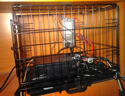
Here is a Faraday cage built for a Yaesu FT-891 radio, with the intent of containing any residual emissions within the cage and ensuring that the signal will pass through the antenna instead of being radiated in all directions from the radio.
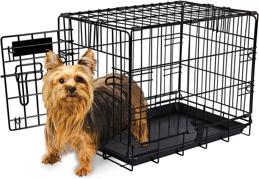
For shoppers, the cage was cheap to find and it is no more than a cheap cage for small pets with the only condition that the cage should be built out of metal and not plastic.
As can be observed, the power source is also kept within the cage - and why not, given that switching power supplies do generate residual emissions that could just as well be contained by the same cage. Intuitively, in case an USB hub would have to be used, compared to the power supply, the USB hub should be placed outside of the cage due to the EMI generated inside the cage being able to influence the circuitry within the USB hub.
Motorcycle Battery as Power Source
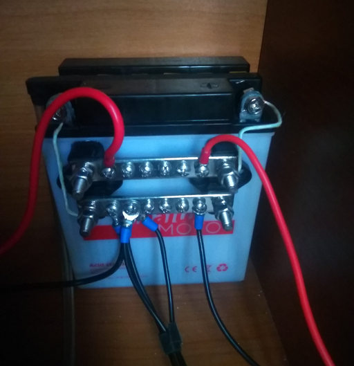
One very cool solution for both portable and fixed station HAM radios is to purchase a motorcycle battery. These batteries are typically cheap acid based batteries that will last forever in case the only device that drains the battery is the radio. For instance, terminal rails can be attached to the battery in order to offer an easy way to connect devices to the battery.
Similarly, in order to charge the battery, a typical car battery charger can be used to recharge and maintain the battery. Doing so would reduce the noise level to nothing as well as decoupling the radio from other nearby circuits such as a landline.
Morse (CW) Learning Method
Most experts tend to claim that morse is best learned audibly rather than visually. For instance, even if morse is learned to the point where an operator can broadcast the letters by memorizing the dits and dahs sequences, it is not a guarantee that the same operator can do the reverse and transform the sound patterns back into letters.
That being said, perhaps the following method could yield better results for operators wishing to learn morse code. The method consists in loading up the following clips in a player and then shuffling the playlist such that all letters will be played randomly. The clips consist in the spoken letter, followed by its corresponding dit and dah sequence. In doing so, an operator willing to learn morse, could just listen to the same playlist ad nauseum whilst performing other tasks until, hopefully, the letters and corresponding morse sequence sounds are memorized.
To use the files, download each clip and add them to any player that supports shuffling (or perhaps go through the list alphabetically at first) and play them back.
The original clip is made by greedonever and the letters have been cut up separately in order to be able to listen to the letters individually.
The following list is the reverse of the former where the morse sounds are heard first, followed by the corresponding letter. Ideally, this should stop bias where a listener would just agree with the spoken letter even if the sound is not yet heard.
The 30/70 Rule
As a general trope, the 30/70 rule highlights the fact that only  of a good setup consists in the actual HAM radio hardware and that
  is left over for the antenna. In other words, even if one were to purchase extremely expensive hardware, a solid antenna tuned for the correct band is at least
  more important. Quality HAM radios typically have very many extra features bolted on that are not really needed and barely used. Both sending and receiving, as per the 30/70 rule hinges mostly on a good antenna.
Sound Card Disconnecting during Transmit
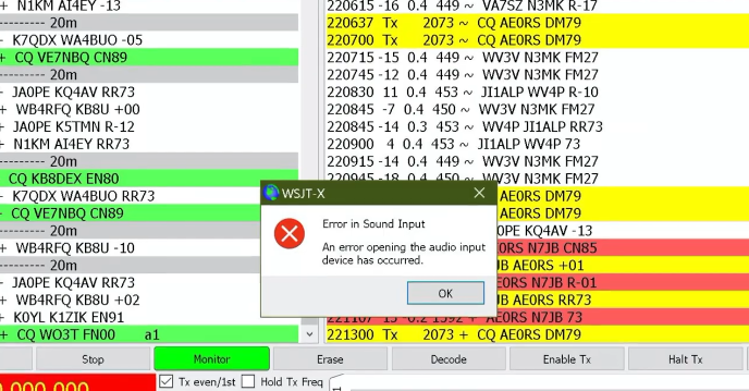
One interesting problem that during transmission, and in particular in digital mode where a sound card is required such as via WSJT-X, it might so happen that the sound card disconnects from the computer, sometimes even requiring the sound card to be reconnected, the radio reset or power cycled. From observation what happens is that after a certain transmit power threshold, the sound card tends to disconnect from the computer, and many times with the transmit power being well below the nominal or selected transmit power.
The most common problem is the lack of a counterpoise or, a counterpoise that shares ground with the radio ground that leads to RF flowing over the outer shield of the antenna cable, right back to the radio and creating interference with the radio and other electronics.
Here are some solutions in order to remedy the situation:
- add a counterpoise wire,
- add counterpoise radials to the antenna,
- add an RFi choke balun to the antenna,
- use a toroid such as FT-240-43 with either 12 or 17 wraps of the antenna around it to reduce RFi,
- ensure that the antenna ground (outer wire, sheath, connector metal) does not share a common ground with the radio common ground
Antenna Voltage Blocking Capacitor
In general, any capacitor placed in-line with an antenna will provide protection from voltage flowing into the radio such that current can be injected into the antenna, for any reason.
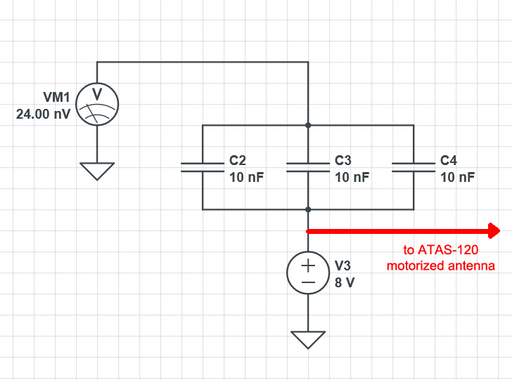
For example, given the MFJ-1925 box that can be used to control an ATAS-120 motorized antenna, the immediate line that feeds into the radio is in series with three  capacitors in parallel through which either
  or
or  will flow unwillingly due to the voltage being on the same line that controls the ATAS antenna.
As the simulator calculated, even though  is fed into the array of capacitors, only
  flow into the radio, which is more than negligible. Even though not illustrated, feeding
  to the capacitor array, reduces the voltage to
  which is still negligible.
Salvaging and Reusing a PL259 Socket as a Cable Extender
Antennas with a magnetic base are typically fairly low quality and have the unfortunate property of allowing rain to seep into the base such that most of the magnet and the other iron-based components will end up rusting. However, these PL259 sockets can be salvaged easily by cutting the plastic base apart and then retrieving the socket.
The making-of of such antennas involves squeezing and distorting the body of the PL259 socket such that it is clamped up by a metal lip that apparently is the only thing holding the PL259 socket in place. Upon removal of the PL259, the PL259 was soaked in some chlorine substance in order to remove any stains of rust, for about a day.
With the rust removed, the antenna is soldered back in place and then using some product packaging a mold is cast with the intent of creating a plastic housing for the jack.
With the form in place and the antenna inserted, molten plastic is poured within the hole alongside the cable.
The antenna socket is then shaped by cutting off the excess packing foam in order to obtain an acceptable and pleasant aspect.
It is entirely possible to keep the entire foam around the socket, or the foam could be trimmed such that only the plastic is visible. It does not matter too much because now the socket and soldered joints are sealed and impermeable.
Creating a Telescopic Arm for an Antenna
Ideally antennas are cleared from buildings and placed as far as possible in order to prevent waves to bounce and be absorbed by the wall itself. Given limited space and constrictions such as an apartment building, it is interesting to create a "telescopic arm" that will allow an antenna to be extended from a balcony thereby clearing a few meters off the building.
Here is the goal of what has to be realized:
The antenna is meant to be fixed after the outer hinge with the arm being able to be extended all the way and then oriented properly upward. A mounting plate is used to hold the antenna in-place and the fixture on the end of the arm is made permanent by using a combination of mechanical fixture, super-glue and JB weld.
Depending on the angle at which the middle segment of the telescopic arm is meant to be bent, a series of holes can be drilled on the side of the arm in order to fit some reinforcements brackets in order to increase the resistance of the arm to torque applied to the arm itself. First, a middle reinforcement bracket is mounted:
Finally, another bracket is fixed at the end of the telescopic arm in order to hold the antenna mounting bracket in place.
With those modifications, the telescopic arm seems sturdy enough to be mounted and used outside the building with the antenna being extended about a meter or more from the side of the wall.
Enhancing Reception Considerably using a Scanner
Whilst HAM radios should be the jack of all trades, and master of all, to turn the phrase, a radio scanner is built to be much more sensitive a reception than a HAM radio that is supposed to accomplish both tasks. Furthermore, a scanner is also built to expeditiously scan a whole band within seconds and using a scanner instead of your HAM radio reduces the wear and tear of the HAM radio (due to the typical relay-layout within a radio that ultimately will degrade over time).
The setup would require two antennas, both tuned for the band meant to be communicated in, with both the scanner and the radio connected to either antennas.
    ^             ^
    |             |
    |             |
+---+---+    +----+----+
|  HAM  |    | SCANNER |
+-- +---+    +----+----+
    | LINE OUT    | LINE OUT
    +------+------+
           |
        +-----+
        | MIX |
        +--+--+
           |
           +--- PHONES
The line out or headphone out are then fed into a mixer, either passive or active, in order to overlay the sounds for the operator. In doing so, and by playing with the sound (and squelch) of the HAM radio and hat of the scanner, the operator can reinforce the sound that they are receiving by letting the scanner fill-in for the reception. One interesting consequence is that the scanner will receive the HAM radio, adding an extra "monitor" feature to the radio if it did not have any and allow the operator to receive their own voice.
Fitting PL259 Antenna Jacks
PL259 is the antenna jack standard that seems to be used predominantly in the HAM radio world such that there are plenty of PL259 jack variants and also everyone has their own way of fitting the jacks. This section explains one take on how to assemble a PL259 antenna jack. First, even though one of the tactile wonders of this jack is that the casing that screws into the counterpart socket does not seem to be able to be removed, the casing can, in fact, be removed by screwing it out the back. After this is done, remember to slide the casing down through the wire in order to ensure that the casing is not forgotten on the outside.
The next part is cutting the antenna cable to size. The length to cut as a simple mnemonic is the total length of the jack. The antenna isolator is then cut down and only a small bit of internal isolator is left over. The reason for cutting down the inner isolator is that the inner isolator that protects the inner signal wire does not fit within the small shaft.
After the antenna is passed through the jack, the jack can then be screwed in and onto the black cable until the jack cannot advance any further. Finally, some solder is used to solder the signal end of the antenna to the shaft permanently (desoldering will be required in order to sever the antenna from the jack). It is up to anyone's best guess whether the copper wires corresponding to the ground should be shortened, but in this case the wires were shortened for the sake of not producing a short when equipment is shuffled around. Finally, the outer casing is brought back and screwed back over the jack and left to wobble.
Ultimately and perhaps the most frustrating part is knowing how much of the two inner and outer isolators to cut, such that the former image should be the core of these instructions.
Antennas & Range
In order for two stations to be able to send and transmit both ways, the radiation pattern of both antennas must overlap. Having said that, the power put out by the radio, is ideally the sum total that an antenna can put out. However, it is possible to change the antenna geometry in order to receive a "better" geometric disposition of the radiation pattern that it generates.
If you want to imagine this better as an easier to understand model, you can think of the sum total of the radio power as a lump of putty of a certain fixed amount of mass. Hence, it is possible to change the geometry of the putty in order to reach certain directions, but it is not possible to reach all directions with the same amount of putty. Even though simplistic, this is the actual model that various antenna patterns run by.
For example, omnidirectional antennas would distribute the putty equally in all directions but, given the fixed amount of putty available, it will not reach as far as a directional antenna that could dispose the putty in a given direction, but not in some other directions and definitely not all directions.
Whip or Monopole Omnidirectional Antennas
The whip or monopole directional antenna is a specific type of dipole, where only the top part of the dipole is used for radiation. The whip distributes the radiation all around the vertical axis equally and it is the default antenna of choice if no direction in particular is sought after.
![Equation $$
\begin{tikzpicture}
\draw[-] (-5, 0) -- (5, 0);
\draw[-, line width=1mm] (0, 0) -- (0, 1);
\draw[color=magenta] (0, 0) arc(0:180:1cm) -- cycle
\draw[color=magenta] (2, 0) arc(0:180:1cm) -- cycle
\filldraw[color=magenta, pattern=crosshatch] (-5,0) rectangle (5,-1);
\end{tikzpicture}
$$](/lib/exe/fetch.php?media=wiki:latex:/img14681529b2c78375b51abdb5eb436b7b.png)
The whip antenna is very popular with car antennas for the citizen band and are typically sold as quarter-wave antennas to be attached via a magnetic mount onto the chassis of the car.
Note that one of the major drawbacks for a monopole is that the antenna needs a reflector to work against and that is typically the ground. For car chassis mounted antennas, the actual "ground" is considered to be the car chassis but note that suspending a monopole antenna above ground will not work and the antenna will need a counterpoise to work as the ground plane.
Dipole Antenna
The dipole antenna is an antenna with two elements, joined together in the middle by a balun that can be built out of solid materials or just by using wire. A monopole is a dipole antenna where only one half of the antenna is used.
![Equation $$
\begin{tikzpicture}
\draw[-] (-4, 0) -- (4, 0);
\draw[-,line width=1mm] (0, -1) -- (0, -0.07);
\draw[-,line width=1mm] (0, 0.07) -- (0, 1);
\draw[color=magenta] (-2, 0) ellipse (2cm and 1cm);
\draw[color=magenta] (2, 0) ellipse (2cm and 1cm);
\end{tikzpicture}
$$](/lib/exe/fetch.php?media=wiki:latex:/img38bd5f77646b160cbeb8b31be43bad31.png)
Dipole antennas are frequently used in portable scenarios, such as for SOTA or POTA for which carrying a large antenna would not really be feasible, such that a dipole antenna is used instead.
Yagi-Uda Antenna
A Yagi-Uda antenna consists in a mast, a main beam (the central axis element) and multiple radials that run through the beam and protrude out of both sides. This is easy to remember if you think that the radials are meant to somehow "pull" the signal forward, from the mast to which the Yagi is attached to, in order to achieve the forward-ellipse radiation pattern.
![Equation $$
\begin{tikzpicture}
\draw[-] (-4, 0) -- (4, 0);
\draw[-,line width=1mm] (-2, 0) -- (4, 0);
\draw[-,line width=1mm] (-2, -.5) -- (-2, .5);
\draw[-,line width=1mm] (-1, -.5) -- (-1, .5);
\draw[-,line width=1mm] (0, -.5) -- (0, .5);
\draw[-,line width=1mm] (1, -.5) -- (1, .5);
\draw[-,line width=1mm] (2, -.5) -- (2, .5);
\draw[-,line width=1mm] (3, -.5) -- (3, .5);
\draw[color=magenta] (-2, 0) circle (.5cm);
\draw[color=magenta] (1.5, 0) ellipse (3cm and 1cm);
\end{tikzpicture}
$$](/lib/exe/fetch.php?media=wiki:latex:/img93848e5028f881b8b02793bc3d786a81.png)
Yagis are phenomenal directional antennas and are perhaps the most commonly used for HAM radio at sub-GHz frequencies in order to reach over very large distances. A Yagi is usually build depending on the frequency range that it is supposed to be used with and the frequency is also the one that specifies where the radials are to be placed, what distance there should be between them as well as the thickness of the materials.
Magnetic Loop Antenna
A magnetic loop antenna is a circularly shaped antenna with a radiation pattern similar to a dipole or a monopole. Typically a magnetic loop antenna is used in enclosed spaces or indoors because it does not use too much space or is easy to suspend in front of a window.
![Equation $$
\begin{tikzpicture}
\draw[-] (-4, 0) -- (4, 0);
\draw[-,line width=1mm] (-1, 0) -- (1, 0);
\draw[color=magenta] (-2, 0) ellipse (2cm and 1cm);
\draw[color=magenta] (2, 0) ellipse (2cm and 1cm);
\end{tikzpicture}
$$](/lib/exe/fetch.php?media=wiki:latex:/imgcb3955a0c7eb45dd40c6b7384801854d.png)
Note that the geometry of the magnetic loop antenna is misleading and the antenna radiates out of the perimeter of the circle like a doughnut, with the center of the circle actually being a singularity point with no radiation. In other words, the side of the loop / circle is what must be pointed in a specific direction.
Adding a Lightning Arrestor
A lightning arrestor is cheap device that allows the antenna of a radio to be grounded such that any lightning strike will be guided to earth instead of striking the radio. Internally, the lightning arrestor works typically using a gas chamber that will connect the main antenna feedline to the ground in case the number of amperes running through the wire exceeds any tolerance threshold that would correspond to the normal usage of the antenna.
The following is a USD12 device that connects in-line with the antenna and must be grounded to a proper earth ground. In the depicted image, the grounding is realized by pulling a copper wire to a metal collar that will latch onto a pipe that leads to the general ground.
The placement of the lightning arrestor, ideally, matches the ideal placement of a common mode choke and preferably the arrestor should be mounted somewhere outside the shack in order to not carry the lightning inside. Note that placing the arrestor too close tot the antenna is also not too great because the lightning might strike the cable instead of the antenna, thereby bypassing the lighting arrestor altogether.
In this case, the lightning arrestor was placed directly in-line with the 1:1 unun common mode choke designed to remove reflected waves and reduce EMI right outside the radio shack as shown in the image.
Converting an Angle Coaxial Antenna Socket (SO253) to Straight-Through Connector
Brackets exist that allow the placement of a CB antenna as a mirror mount, but for most of them there is some element of counter-intuitive design that makes the ensemble difficult to understand, namely the placement of the cable that comes out of the SO-253 socket seems sideways.
It does not make sense to have the cable exit sideways and it leaves a lot of room underneath the antenna.
However, the connector can be cut down and rewired to be a straight-through SO253 socket connector. The first step is to cut the cable and then the back part of the large antenna connector can be dug out using a screwdriver to reveal a center pin that the trimmed cable can connect to. Unfortunately, there is no grounding pin, the ground being provided by a small cylindrical ring that is clamped onto the antenna ground and then fed into the connector. However, the cylindrical ring leaves a hole in the side of the antenna connector that the grounding can loop around and then be soldered into place.
Unfortunately, removing the antenna requires the plastic holder to be cut such that a replacement must be made. One good usage of hot melt glue is to use hot melt glue along with a bit of painter's tape to create a new holder for the antenna socket.
Frequency Filtering
When transmitting an antenna radiates on a given frequency that the radio is set by the operator to oscillate on however that also produces tertiary oscillations that are not congruent with the frequency being selected. The resulting "unwanted" oscillations are frequency radiations that are off-frequency and might interfere with other equipment. With that said, wouldn't it be handy to be able to somehow attenuate any frequencies that are not meant to be emitted or, conversely maybe, just "pass" a slice or frequency range (conventionally called a "band") that the operator intends to transmit whilst hampering any other frequencies?
For that purpose frequency or band filters exist, perhaps the most well-known "Low-pass Filters" LPF or "High-pass Filters" HPF.
In order to not confuse LPF and HPF, the mnemonic trick is to focus more on the keyword "pass", such that "low-pass" means to "allow low frequencies (and hamper high frequencies)", respectively "high-pass" implies to "allow high frequencies (and hamper low frequencies)".
Of course, there exist more sophisticated "band-pass" or "band-stop" filters that allow, respectively hamper a certain frequency range meaning that the "passing" or "stopping" is done on both ends.
For HAMs
Depending on your views on HAM radio, the classic HAM radio zone lies between  and up to
  with a common limit being 10/11 meters. This implies that classic HF (high-frequency) HAM radio equipment, before VHF (very-high frequency) or UHF (ultra-high frequency), that is meant for HAM radio operators are not meant to transmit beyond
  (6m band).
With that said, any tertiary oscillations beyond  is literally unneeded junk that might end up interfering with other electronics such as household radios or TV sets, such that getting rid of any emissions beyond
  would be great. Emitting off-frequency is the usual method of getting into trouble with neighbors and the authorities due to unwittingly producing interference.
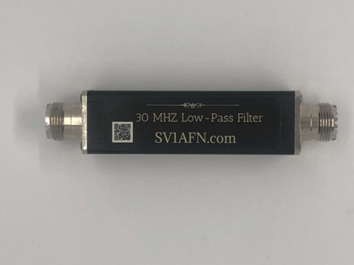
One solution is to use a low-pass filter such as a filter made by RM Italy.
The device even has a nice graph printed right onto it showing the user which frequencies it will pass and which frequencies it will reject. In this case the RM Italy 24-30Mhz Low Pass Filter 35/600-600 Watts passes all frequencies up to  and rejects anything beyond
  . Conveniently, the frequency bands along with the attenuation produced by the filter are noted onto the chassis showing that anything below the range
  to
to  will have less than a
  attenuation, that anything within the range
  to
to  will have less than a
  attenuation and that any oscillations after
  will be dampened by
  with more than
  attenuation after the
  mark (which prevents interfering with commercial radio channels, typically ranging between
  and
and  ).
).
The device is rated at  , which is overkill given single-side band (SSB) capabilities where it is possible to reach around the planet digitally even with less than
  . The RM Italy 24-30Mhz Low Pass Filter 35/600-600 unfortunately seems to pinch the 6m band a little given its specification and given that
  has been introduced as a valid HAM radio frequency, the filter might not be appropriate for newer HAM radio models.
Otherwise, this device, albeit costly, is very effective in making sure that the station does not interfere with other equipment.
For Input Current
Circuits pass input ripple with the irregularities propagating from one stage to the other affecting the output. With that said, it makes sense to have a frequency filter on the input line such as the household or shack A.C. power line in order to attenuate the ripples produced by other equipment. This can be accomplished even using a single capacitor and perhaps a resistor, as per the writeup on the electronics page that studies a very simple capacitive low-pass filter. Ripple on the A.C. input line to a HAM radio will have that ripple reflected in the transmission of the radio and even quite clearly very similar to the typically perceived "hum" that is indicative of reverse current when the antenna has insufficient ground to work with (and needs a counterpoise) or a (ferrite) common-mode choke is necessary.
In fact, widely-used ferrite beads are just that, a low-pass filter that ensures that high frequencies do not pass through. Trivially, a ferrite bead or core is both convenient and cheap, such that it is always a preferred solution but most of the time a proper capacitive filter is the best to have and fortunately they are not too expensive either. Consequently, for HAM radio usage little details such as line-ripple matter very, very much because the clarity of the transmission or reception is the whole purpose of the hobby; this, say, compared to having an extremely clear signal for a washing machine that would really not care all that much.
Filters scale up and one can then add an inductive high-pass filter to the low-pass filter thereby achieving a band-pass filter in order to ensure the only the very best frequency survives and that all ripples are eliminated. More advanced filters incorporate torroids inside by default, coils, capacitors and resistors in order to create a band-pass filter that stabilizes the A.C. current.
With that said, it is a great idea to not "save up money" on signal clarity when operating an expensive radio which is really being callous. Filters are relatively cheap as well as ferrite beads and there is no counter-indication to using as many of them as possible. In fact, advanced filters implement a capacitor network (sometimes even using batteries!) that pass the current through the whole pipline where it is dampened and adjusted at every step. In DC circuits, filters a present before every component that is known to be sensitive to input current ripple.
For the contact, copyright, license, warranty and privacy terms for the usage of this website please see the contact, license, privacy, copyright.
