Table of Contents
About
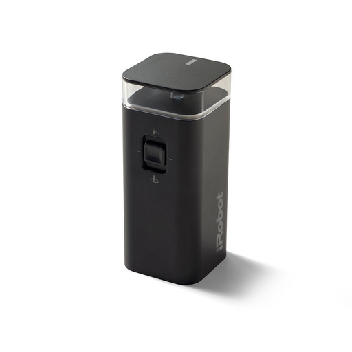
The Roomba Virtual Wall Barrier can be modified in order to remotely activate or deactivate the barrier with the help of some IoT technologies.
For this project, the goal is to be able to remotely activate and deactivate the tower in order to block the Roomba and then perhaps to allow the Roomba to pass very similar to the classic Roomba lighthouse.
Requirements
- WeMoS ESP8266,
- LiPo battery at
 ,
, - EE2-3TNUH low profile latching relay at
 ,
, - wires,
- soldering equipment
Block Diagram
The virtual wall barrier will have one of the power leads interrupted and connected to the latching relay. In turn, the relay will be activated and deactivated by the ESP8266 via two of the digital output pins. The ESP8266 will be powered by a LiPo battery.
Walkthrough
The benefits of using a latching relay is that the impulse from the ESP8266 has to only be applied once and then the pin can be deactivated such that the relay will retain its position over power cycles.
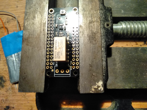
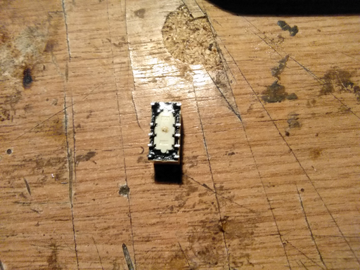
The EE2-3TNUH is a low-voltage dual-latching relay that is activated and deactivated by supplying  to the pins corresponding to the built-in coil. Since the EE2-3TNUH relay is hard to come by, a EE2-3TNUH has been salvaged off a FeatherWing relay hat by applying heat to the back of the board as well as using some soldering wick to pry the relay off the board.
With the relay detached, the contacts have been cleaned and the circuit isolated using a tone generator by applying voltage to the coil pins of the relay.
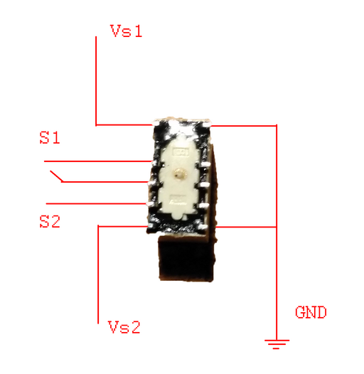
Since the plan has been to just interrupt the virtual wall barrier battery feed, just one of the switches from the latching relay has been used. Namely, the ground pins have been connected together and to the ESP8266 common ground, the  pin has been connected to the digital output pin
 D5 of the ESP8266, the  pin has been connected to the digital output pin
 D6 of the ESP8266 whilst the two pins of  have been connected to the battery terminal and the PCB battery terminal using some wires.
In other words, when the ESP8266 sets D5 to high and then to low, thereby transmitting a short  impulse, the switch
  makes the connection between the virtual wall barrier battery and the virtual wall barrier PCB thereby turning the virtual wall barrier on.
Conversely, when the ESP8266 sets D6 to high and then to low, the switch  disconnects (and the switch
  connects but the pins of the switch
  are floating) thereby turning the virtual wall barrier off.
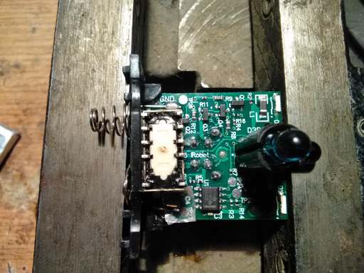
To make that happen, the positive terminal on the virtual wall barrier is desoldered and isolated from the board such that both the terminal and the PCB will connect together through the  switch of the latching relay.
The relay is then mounted onto the virtual wall barrier PCB using some strong double sided adhesive.
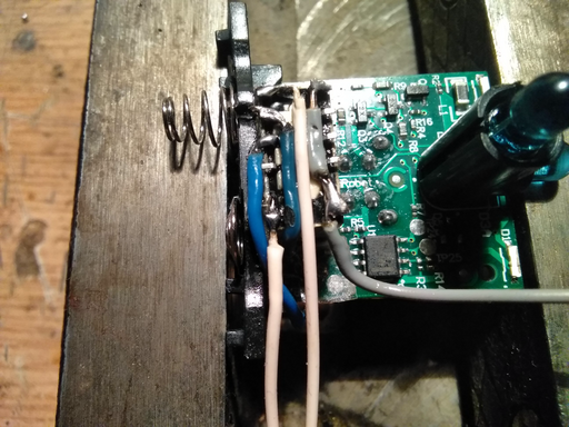
With the relay in place, traces are drawn from all the relevant pins of the relay. Note that the right-most upper and lower pins have been bridged together since they represent the common ground of the latching relay.
Now that the relay has been all wired up, the PCB and the relay are cleaned with some isopropyl alcohol and some masking tape applied just to protect the cables and the traces.
The ESP, battery, relay and virtual wall barrier PCB are now all wired up and ready to be placed inside the virtual wall barrier.
Luckily, everything fits inside and the cables are arranged from the top part of the virtual wall barrier in order to not mask the IR LEDs of the Roomba virtual wall barrier.
Programming the ESP8266
The ESP8266 has been programmed using the Arduino IDE, by downloading the ESP8266 boards package, the ArduinoJson library, the PubSub MQTT library and then by uploading the Wizardry and Steamworks GPIO tool sketch.
The Wizardry and Steamworks GPIO tool will make the ESP8266 connect to the local IoT Wifi network and subscribe to an MQTT server listening on a server for connections.
Now, by sending a payload such as:
{
  "pin": 5,
  "state": "on",
  "action": "set"
}
followed by:
{
  "pin": 5,
  "state": "off",
  "action": "set"
}
the digital output pin D5 of the ESP8266 will activate the EE2-3TNUH latching relay and power on the Roomba virtual wall barrier.
Conversely, by sending a payload such as:
{
  "pin": 6,
  "state": "on",
  "action": "set"
}
followed by:
{
  "pin": 6,
  "state": "off",
  "action": "set"
}
the digital output pin D6 of the ESP8266 will deactivate the EE2-3TNUH latching relay and the virtual wall barrier will be switched off.
Node-Red
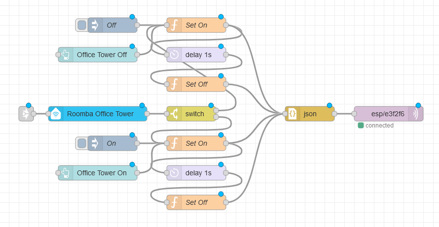
Using node-red, automation is rather trivial and an example flow could look like the following:
The flow is very symmetric, where the upper half is dedicated to turning the Roomba virtual wall barrier on by setting the ESP8266 pin high and low whilst the bottom half is dedicated to turning the Roomba virtual wall barrier off.
Perhaps the only non-trivial component here is the Alexa node that will allow toggling the Roomba virtual wall barrier using the Alexa voice assistant.
For the contact, copyright, license, warranty and privacy terms for the usage of this website please see the contact, license, privacy, copyright.
