Table of Contents
About
Typically non-expensive HAM radios such as car or truck-mounted citizen band radios do not benefit from a line-input even though they typically provide an audio output to be typically routed to an amplifier. It would be nice to be able to interact with the radio by connecting a computer or different playback device in order to broadcast short audio or music clips over the radio. In some cases, such as using digital over  ,
,  or even
  bands via software such as
 js8call, audio playback over the radio is required.
The main challenge is that radios are not typically broadcasting all the time, mainly because that would mean that the frequency would be jammed as well as the radio probably ending up damaged due to the high power utilization. That being said, it is necessary to not only create a line-feed to the radio but also additionally make sure that once the playback has stopped, the transmission will be ended and the radio emissions turned off.
The following document illustrates using a very cheap and safe circuit based on an ESP8266 that is capable of detecting the sound levels from a  input jack, going live when music is detected on the sound input by setting PTT (Push-to-Talk) to low and then feeding the music into the transmission. After the music has played, the circuit should detect that there is no more sound on the sound input and then close the transmission by resetting PTT.
The former mechanism is typically marketed as VOX; the ability of a microphone device to automatically start and stop depending on whether sound is detected, contrary to having to manually press a button.
Requirements
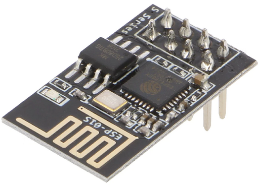
- an ESP8266, mainly used for elegance, perhaps an ESP-01S (SS4H-ESP-01) module of size
 by
by  and rated at about
  that has just the necessary amount of GPIO pins for the VOX circuit (note that for simulating, an ESP32 is used instead, but that will be changed to the ESP-01S in the final realization)
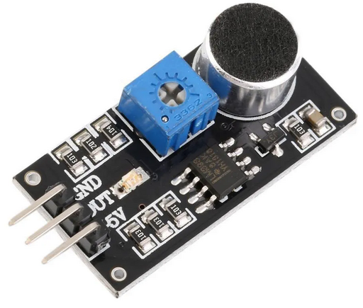
- an IoT sound sensor with a digital output
the digital sound sensor will output either 0 or 1 depending on an adjustable threshold controlled by the onboard potentiometer when sound is detected. The intent is to remove the microphone and feed sound directly to the circuit and adjust the coupling such that the circuit will detect line-in sound input levels
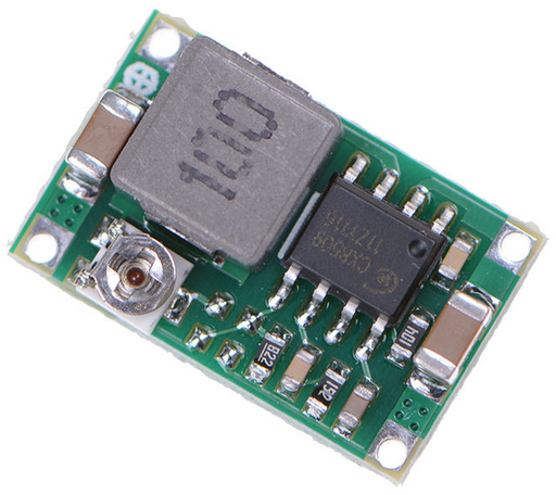
- a variable buck step-down circuit that will provide the circuit with
 (that will later be divided to
  for the ESP)
- a custom transistor-based switch that will be used to control the PTT line of the HAM radio,
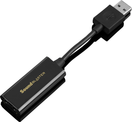
- for the HAM radio, a very cheap but very good sound card would be the SoundBlaster Live 3! that connects to an USB port and provides both microphone in and headphones out; the microphone in is used to play the output of the HAM radio and the headphones out will be connected to the circuit being designed
any other USB soundcard would do. One thing that might be important is that the SoundBlaster Live 3! does not seem to like to be suspended such that it might behave erratically in case the computer hibernates.
- a
 sound jack in order to feed audio into the HAM radio,
 - the usual crafting equipment; Dremel, soldering iron, etc
Detecting Sound Input Levels
Looking at the diagram, one apparent problem is that the HAM microphone is not decoupled from the line input, however that is not a problem due to the microphone sensor having the ability to be calibrated such that the coupling threshold can be set anywhere any residual line noise above zero levels. In other words, it is partially the responsibility of the line-in feeder (PC, MP3 player or otherwise) to ensure that when sounds are not being output to the HAM, that the levels remain at zero levels as well as the microphone sensor to be calibrated via the potentiometer to correspond to zero level input on the line-in.
That being said, whenever sound gets passed to the line-in jack of the HAM radio, the circuit will set PTT to zero levels and start emitting the sound over the waves. When the line-in levels drop to zero, the circuit will pull up PTT and terminate the transmission. Concomitantly, when the operator wants to broadcast, they manually push PTT as usual and transmit. In case the radio is broadcasting, having pulled down PTT and the operator additionally manually pushes PTT, then nothing spectacular happens except that the operators voice would most likely be mixed with the music.
Software Debouncer
The levels generated by the microphone sensor are digital and can be represented as a square wave having a frequency correlated to the cutoff threshold of the microphone sensor. In other words, if one were to feed sound directly into the microphone leads of the microphone sensor, one would notice that the circuit will generate a series of digital 0s ( analog), and
 1s ( analog) depending on the setting of the onboard potentiometer. For instance, plotting the digital output of the microphone sensor as voltage over time would end up in a series of blocks with no distinguishable period.
V     ^
      |
      |
3.3V  |  +------+             +------+  +------+
      |  |      |             |      |  |      | ...
      |  |      |             |      |  |      |
    0 +--+------+-------------+------+--+------+------------->
                                                            t
         |<---->|<----------->|<---->|<>|<---->|

         silence     music     silence   silence

                                     music
The microphone sensor used just so happens to be designed to output a digital high when the analog input levels of the microphone are set to low when no music is playing and a digital low when audio is detected on the analog input levels of the microphone. In principle, even if counter-intuitive, it seems to be a design characteristic of the microphone sensor, and given that everything after the analog microphone will be processed digitally, it makes no difference except switching the circuit and programming logic around.
In order to observe the effects of the digital fluctuations of the microphone sensor, a software tone-generator can be used (in this case, Daqarta for Windows) that allows various waveforms to be played through the sound card output. For instance, using Daqarta, a sine-wave tone is generated and played through the line-in of the VOX circuit being designed in order to observe the fluctuating ESP LED that will, in the final version, be responsible for opening and closing the HAM PTT.
Even though Daqarta for Windows looks like a tribute to the 90s:
(Interstellar Research! How cool is that?! Remember the first game ever created was programmed on an oscilloscope!)
it is, to its merits, a very convenient program that allows generating waveforms as audio and playing them through the sound output.
Daqarta is configured via the menu Edit->Start Preferences (...) to output audio through the sound card that is connected to the VOX circuit being designed. Then, the generator is used to generate a sine wave and play it through the sound card. A sine-wave is chosen instead of a square wave since a sine-wave seemed like a better abstraction of regular audio such as music.
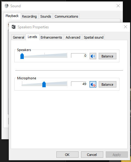
The sound card playback levels are then controlled using the Windows built-in sound level properties for the soundcard.
Using an example Arduino sketch and setting ledPin to LED_BUILTIN as well as configuring the microphone sensor pin to pin 4 for the VOX circuit being designed the following sketch can be used to demonstrate the effects of the wave generated by Daqarta:
// Circuits DIY
 // For Complete Details Visit -> https://circuits-diy.com
int ledPin=LED_BUILTIN;
int sensorPin=4;
boolean val =0;

void setup(){
  pinMode(ledPin, OUTPUT);
  pinMode(sensorPin, INPUT);
  Serial.begin (9600);
}

void loop (){
  val =digitalRead(sensorPin);
  Serial.println (val);
  // when the sensor detects a signal above the threshold value, LED flashes
  if (val==HIGH) {
    digitalWrite(ledPin, HIGH);
  }
  else {
    digitalWrite(ledPin, LOW);
  }
}
Here is what the project looks on a breadboard when the sine wave is fed through the soundcard to the circuit:
Since the period is variable depending on the microphone sensor, the HAM PTT would end up being pulled up and down chaotically which is definitely undesirable since the broadcast should be continuous. In other words, what would be ideal, is that once a digital 0 is sensed by the microphone sensor, the HAM PTT would pull low and start broadcasting. For a defined and renewable time-period (if other digital 0s are sensed), the circuit should hold the HAM PTT to high. After some definable time  , and additionally given that the microphone generates only digital highs (
1s) the circuit should pull the HAM PTT up high and stop the broadcast.
This is called a debouncer and is equivalent to ALARM(2) in system programming. In order to better illustrate the functionality of the circuit, the following graph plots the digital output of the microphone sensor versus the digital trigger of the PTT button on the HAM radio.
                      V ^
            ^           |
            |        Vc +---------+                                               +----------- . . .
            |           |         |                                               |
            |           |         |                                               |
            |           |         |                                               |
            |           +---------+-----------------------------------------------+---------------->
     PTT    |           |
  (digital) |           |         |<----------------------------------+---------->|
            |           |                              alarm               at
            |           |
            |           |         |<--------------------------------------------->|<---------- . . .
            v           |                     ON (broadcasting)                      OFF (silent)
            -           +
            ^           .
            |           .
            |           .
            |           +
            |           |
     mic    |           |
  (digital) |      3.3V +---------+  +---+     +--+    +-----+        +--------------------- . . .
            |           |         |  |   |     |  |    |     |        |
            |           |         |  |   |     |  |    |     |        |
            v           +---------+--+---+-----+--+----+-----+--------+-------------------------->
                                                                                                t

                        |<------->|      |<--->|        . . .         |<-------------------- . . .
                          silence         music                               silence
What happens here is the following:
- initially, there is no sound passed to the VOX line-in circuit of the HAM radio such that PTT is pulled high and thereby not broadcasting,
- audio is played through the VOX line-in circuit such that the microphone sensor generates a
0on its digital output, PTT is pulled low and the HAM radio starts broadcasting the line-in audio, - the ESP installs a software-defined alarm
 , for example a
  alarm such that
  and as long as digital
 0s are output by the microphone sensor, the alarm is reset,
 - after the audio stops playing through the line-in, the ESP alarm
 runs to the end and the ESP pulls PTT to high such that the HAM radio stops broadcasting.
The new software is flashed to the ESP to implement the debouncer with software:
#include "TickTwo.h"

const int LED_PIN = D5;
const int MIC_PIN = A0;
const int PTT_PIN = D8;

// irrelevant TickTwo.h semantics
void pttClose();
TickTwo ticker1(pttClose, 0, 1, MILLIS);

bool transmitting;

void setup() {
  // configure PTT pin as an digital out
  pinMode(LED_PIN, OUTPUT);
  pinMode(PTT_PIN, OUTPUT);

  // configure MIC pin as a digital input
  pinMode(MIC_PIN, INPUT);
  // DEBUG
  //Serial.begin(9600);

  // deactivate PTT transistor switch / PTT low (start broadcast)
  digitalWrite(LED_PIN, LOW);
  digitalWrite(PTT_PIN, LOW);
  // alarm(MIN)
  ticker1.start();
}

void loop() {
  // irrelevant TickTwo.h semantics
  ticker1.update();

  // read the MIC pin
  int val = analogRead(MIC_PIN);

  // DEBUG
  //Serial.println(val);

  // if mic sensor is low (audio playing)
  if (val == 1024 && !transmitting) {
    // activate PTT switch / PTT low (start broadcast)
    //Serial.println("PTT activated...");
    digitalWrite(LED_PIN, HIGH);
    digitalWrite(PTT_PIN, HIGH);

    // alarm(5000)
    ticker1.interval(2500);
    ticker1.resume();
    transmitting = true;
    return;
  }

  transmitting = false;
}

void pttClose() {
  // deactivate PTT transistor switch / PTT low (start broadcast)
  //Serial.println("PTT deactivated...");
  digitalWrite(LED_PIN, LOW);
  digitalWrite(PTT_PIN, LOW);
  transmitting = false;
}
Now, once sound is being played back through the soundcard headphones and fed to the VOX circuit being designed, the ESP will pull PTT to low and keep PTT to low thereby transmitting. Once the audio output is stopped, the alarm elapses  and then the ESP will pull PTT to high thereby ending the broadcast.
Note that for both cases, Daqarta had been generating the same sine wave continuously and that the effects are different just due to the ESP being programmed differently.
It is observable that at some point during the video, the audio feed is cut off since the second green LED on the microphone sensor goes dark but the blue LED is still on thereby waiting  for a continuation of the audio feed but eventually turning off. Right now the debouncing delay is coded to be
  but the time will be eventually converted to a constant for the final version.
For most HAM radios, holding the PTT down and broadcasting has the effect of both keeping a frequency busy and thereby jamming other users in the radio's range, as well as heating up the amplifier transistors till they eventually give in and burn out. Given transmissions, a  pause is a reasonable timeout after which it would make sense that the broadcast would end. Typically, for playing back audio from a computer, the response time of the sound card greatly outweighs the HAM radio circuitry PTT trigger response such that
  should be ample time for a wait duration.
Calibration
One step was omitted and namely the calibration of the microphone sensor such that when the sound card does not play any sound the microphone sensor should not be triggered. Even though, intuitively, the sensor has no way of being triggered without any signal on the microphone PCB traces, practically the sensor is quite sensitive such that by rotating the potentiometer it is possible for the sensor to trigger anyway.
The calibration method is straight forward:
- generate a sound wave on the output of the sound card and feed it to the microphone,
- ensure that the sensor is triggered (second green LED as well as blue LED if connected to the ESP),
- mute the audio,
- rotate the potentiometer on the microphone sensor till the green trigger LED turns completely off (and a little more)
As an ending note for this section, there is one foreseeable problem mainly due to the microphone sensor having only a digital output. Specifically, there is no way to calibrate the microphone by flashing the ESP meaning that if the sound card ever changes, the microphone sensor might have to be recalibrated via the potentiometer. By contrast, would the microphone have been an analog microphone, then the threshold could have been adjusted via software by flashing the ESP over OTP. That being said, in practice, it mostly should be the case that no recalibration is necessary due to sound cards generally behaving mostly the same - trickle noise on the sound output when the sound is muted for a PC sound card would indicate quite a crap sound card.
Voltage Divider
Another part of the project that can be realized at this time is the voltage divider that would supply the ESP with  such that the microphone sensor can be powered by
  from the DC buck step down regulator. At this time an ESP32 is used that accepts
  as input but the smaller ESP-01S can only be powered by
  .
.
Unfortunately, a voltage divider would not work due to the extra internal resistance of the ESP-01S that would end up changing the input voltage. A better solution is to use an LM1117 or ASM1117 voltage regulator. Several circuits are illustrated within the datasheet, but the most straight-forward circuit that would be needed to drop down  to
to  would be the fixed output regulator schematic:
              +-------------+
          Vin |             | Vout
+ +---+-------+    LM1117   +-------+------->
      |       |             |       |
      |       +------+------+       |
      -              | GND          -
  C1  -              |              -  C2
      |              |              |
      |              |              |
- +---+--------------+--------------+------->
                     |
                    --- GND
                     -
Typical values of the capacitors range between  and
and  and are given by the datasheet itself. LM1117 typically provides up to
  of output which is eight times more than what the ESP-01S needs. Fortunately, for Arduino and IoT ready-made LM1117 circuits are found and to be purchased in bulk. The form factor for these modules is usually the SOT-223 form factor and the LM1117 is minimal enough to not occupy space.
Programming the ESP-01S
The ESP-01S is typically available without a development board and hence no USB capabilities such that an USB-to-Serial programmer must be used in order to flash the Arduino sketch.
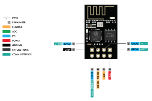
From the board pinout as well as some knowledge about the ESP-01S, the following connections must be made to the USB-to-Serial programmer in order to successfully be able to upload a sketch:
| ESP-01S pin label | USB-to-Serial |
|---|---|
VCC |  |
GND | GND |
U0TXD | RX (?) |
U0RXD | TX (?) |
GPIO0 | GND |
The mapping of U0TXD to RX and U0RXD to TX is uncertain: certain sources claim that the ESP-01S does not need the lines inverted, in which case, the schematic should be terribly wrong. Regardless, reversing serial lines does not usually toast the hardware such that checking both should be fine. Whilst programming, in case the Arduino IDE displays the usual programming dots but interrupted by underscores, then it is a good indicator that RX and TX are the wrong way around.
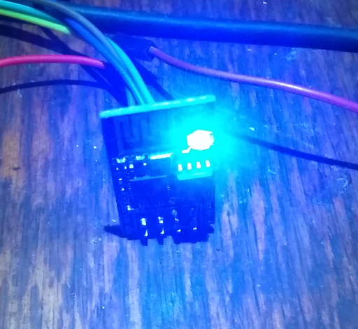
Additionally, the Arduino IDE must have the board set to "Generic ESP8266 Module" for the programming to succeed. In order to test, the Blink example has been used in order to make the ESP-01S blink the blue LED intermittently.
Compared to the development-style boards, note that once the sketch is uploaded, the GPIO0 to GND connection must be severed and the ESP-01S restarted for the sketch to start executing.
The same flashing procedure is now repeated with the sketch from the previous section in order to get rid of the ESP32 board and repeat the tests with the ESP-01S but with MIC_PIN mapped to GPIO3. Similarly, a new pin is introduced that will be responsible for pulling PTT low in order to make the HAM radio broadcast the audio signals. The altered sketch would be the following:
#include "TickTwo.h"

const int LED_PIN = LED_BUILTIN;
const int MIC_PIN = 3;
const int PTT_PIN = 1;

// irrelevant TickTwo.h semantics
void pttClose();
TickTwo ticker1(pttClose, 0, 1, MILLIS);

void setup() {
  // configure PTT pin as an digital out
  pinMode(LED_PIN, OUTPUT);
  pinMode(PTT_PIN, OUTPUT);

  // configure MIC pin as a digital input
  pinMode(MIC_PIN, INPUT);
  // DEBUG
  //Serial.begin(9600);

  // deactivate PTT transistor switch / PTT low (start broadcast)
  digitalWrite(LED_PIN, LOW);
  digitalWrite(PTT_PIN, LOW);
  // alarm(MIN)
  ticker1.start();
}

void loop() {
  // irrelevant TickTwo.h semantics
  ticker1.update();

  // read the MIC pin
  boolean val = digitalRead(MIC_PIN);

  // DEBUG
  //Serial.println(val);

  // if mic sensor is low (audio playing)
  if (val == LOW) {
    // activate PTT transistor switch / PTT low (start broadcast)
    digitalWrite(LED_PIN, LOW);
    digitalWrite(PTT_PIN, HIGH);

    // alarm(5000)
    ticker1.interval(5000);
    ticker1.resume();
  }
}

void pttClose() {
  // deactivate PTT transistor switch / PTT low (start broadcast)
  digitalWrite(LED_PIN, HIGH);
  digitalWrite(PTT_PIN, LOW);
}
Note that the new PTT pin HIGH is now set to high whenever the radio is meant to broadcast and this is because the digital signal from the ESP-01S will be used to trigger a different transistor or relay based switch that will pull the PTT line down.
In order to experiment with the new circuit, all components are connected together again, including the new LM1117 voltage regulator, the buck step-down converter as well as a transistor switch circuit.
As per the schematic, the whole circuit is now powered via a  line from a power supply that feeds a variable buck step-down converter. The step-down converter feeds the microphone sensor that is connected via a
  jack to the soundcard headphones. Similarly, the buck step down additionally feeds the LM1117 circuit (bottom red LED) that converts the
  from the buck converter to
  in order to power the ESP-01S. The ESP-01S reaches to the microphone sensor in order to read the digital output via GPIO pin
 3. Additionally, the ESP-01S will set GPIO pin 1 to high whenever the microphone sensor detects audio from the sound card. From the ESP-01S, the PTT pin GPIO 1 is connected to a transistor switch that will connect the two pins together electrically whenever the GPIO pin is set to digital high.
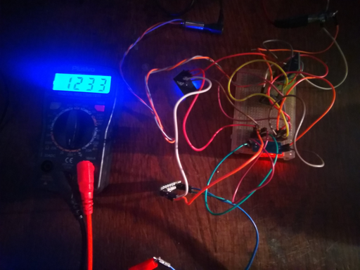
In order to illustrate the effect, an ohmmeter is connected to the two pins of the transistor switch and some music is played through the soundcard. As expected, the microphone sensor lights up (green LED), the ESP-01S blue LED lights up and the voltmeter shows a reading between the two pins of  , which should be sufficient to set the PTT signal to the ground. When the music playback is stopped, the ESP-01S waits for
  and then the connection between the output pins of the transistor switch is severed making the ohmmeter display
 1 (infinite resistance) which should be sufficient to detach the PTT signal from the ground.
One other issue that arises with this circuit is that the 2N3904 within the transistor switch, like any other transistors, require some time for biasing the gate and thereby making or breaking the PTT connection. The result is that the connection is not made instantly and, in fact, with a high resolution ohmmeter it would be possible to observe the resistance change as the GPIO pin is toggled. Perhaps a better solution would be to use a relay, either a solid state reed relay or a mechanical relay in order to reduce the lag.
Practical Implementation
Now that the prototype is functioning as expected, it is time to transplant the circuitry and create a real-world device. One of the applications chosen for this circuit has been a HAM audio injector that will provide input and output to and from the HAM radio. In other words, the device to be created based on this page is an enhanced version of a Yaesu FT-891 data cable with the goal to make the Yaesu start broadcasting whenever an audio signal is played and without having to resort to CAT commands to operate the PTT signal. In doing so, several requirements can be skipped: just open up a music player and play any recording through the sound card included in this product to seamlessly broadcast via the HAM radio.
For this particular application, the Yaesu FT-891 has been chosen as the HAM radio that the final product will be compatible with; however, given the similarities and requirements of other HAM radios, the project has been adapted to be compatible with other devices, even with car or truck CB radios that need only minimal modifications to hook into the input and output audio signals.
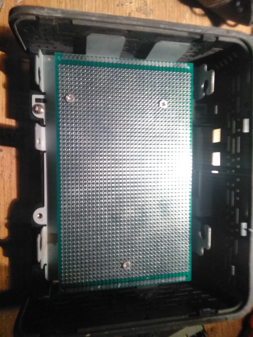
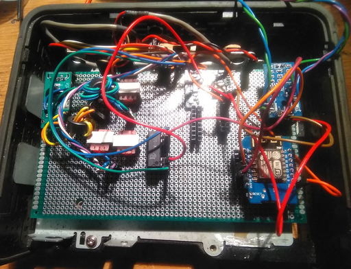
Assessing the required dimensions, it has been deemed that a Western Digital 3.5" Hard-Drive enclosure should have sufficient space to host all the circuitry and perhaps allow some extra features to be added in time. Two blank PCBs are added and holes are drilled to support the electrical components.
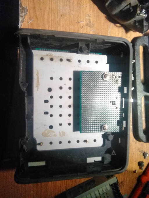
On the top, the WD hard-drive enclosure provides enough space for a large PCB to be placed down and lifted about a centimeter by using PC motherboard raisers. The raisers are glued and screwed to the bottom metal plate of the WD hard-drive enclosure and then the PCB is set in place using screws.
On the bottom part, the second PCB is cut down using a dremel in order to create a PCB shim that will host connectors (USB, audio jacks, power jack, etc.) by even reusing the holes that the enclosure already provides.
The typical functionality of Yaesu audio injectors use the 6pin mini-DIN port (PS/2 connector, in PC terms) on the back of the HAM radio. Two pins, RTYO and DATA IN on the DIN connector provide sound input, respectively sound output but to make the audio injector applicable to other radios, it was decided to build a bridge such that sound input and output can be connected to typical 3.5mm audio jacks on the final product.
The sketch is the following:
3.5mm audio jacks      Yaesu 6pin mini-DIN

input  output
+  +    +  +             -------- RTYO
|  |    |  |            /  *   *----------+
|  |    |  |           |  *     * |       |
|  |    |  |            \  *  *  /        |
mmmm    mmmm             --|--|--         |
----    ----               |  | DATA IN   |
wwww    wwww            +-----+           |
|  |    |  |            |  |              |
|  |    |  |            |  | GND          |
+..+    +..+ sound      |  |              |
|  |    |  |  card      |  |              |
|  |    |  |            |  |              |
mmmm    mmmm            |  |              |
----    ----            |  |              |
wwww    wwww            |  |              |
|  |    |  |            |  |              |
|  |    |  +------------+  |              |
|  +--------------------------------------+
|  |    |  |               |
+  +    +  +               |
|       |                  |
+-------+------------------+
where the input and output lines are pulled from both the 6 pin DIN audio jack as well as additional 3.5mm jacks on the back of the device. Both the 3.5mm ports and the lines pulled from the mini-DIN are isolated using 1:1 transformers with the lines between the transformers being connected to an USB soundcard that will be disassembled and integrated inside the product.
At first, the 3.5mm jacks are connected to the top-most transformers and the cables used between the 3.5mm jacks and the PCB are standard 3 pin PC audio cables.
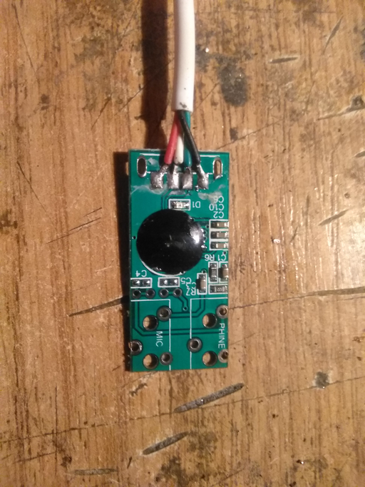
An USB sound card is purchased (similar to the SoundBlaster Live! 3) and disassembled; the 3.5mm jacks on the USB sound card are then removed and the USB cable is desoldered in order to pull the USB port down to the bottom PCB.
Gradually, the circuit from the prototyping board is disassembled and the various components are transplanted onto the PCBs inside the WD hard-drive enclosure.
At some point, the device is powered via  in order to check whether the circuit works. As expected, the
  to
to  step-down flashes the red LED, the microphone sensor lights up green and the ESP flashes the blue LED once during bootup, indicating that the circuit works and power is supplied correctly to the components.
By connecting the device to a PC USB port, the red LED of the USB sound card seems to light up as well, yet again confirming the power test and using an oscilloscope, a signal is injected into the USB sound card and then measured to make sure that the audio side of the device works.
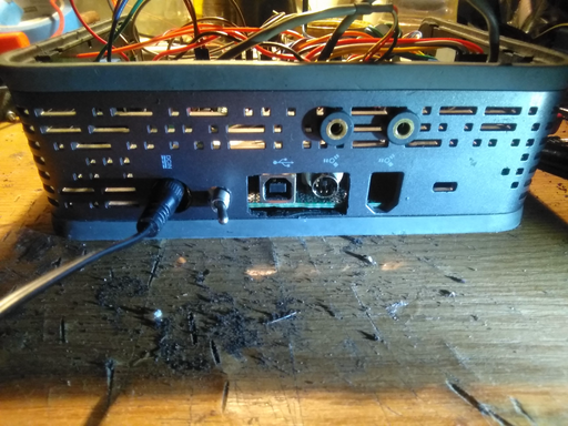
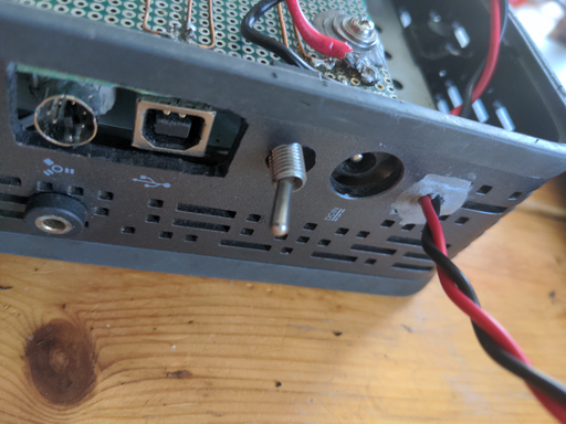
Here is the back of the WD hard-drive enclosure with most of the connectors fitted to the lower PCB board.
with the following purpose (from left to right):
 power connector, to power the entire device (chosen due to vehicle batteries typically supplying
  ),
),- power switch,
- USB connector, connected to the integrated sound card,
- mini-DIN connector, to be connected via a cable to the Yaesu HAM radio,
- two additional 3.5mm audio jacks that allow the device to be connected to any radio that provides input and output audio lines
One of the problems with the ESP-01S seemed to be that holding some of the GPIO pins (other than GPIO0) to either low or high during startup, made the ESP go into programming mode, or at least not boot successfully such that the ESP-01S was replaced with a WEMOS D1 mini that seemed more stable. One of the advantages due to the change was that a  step down was not required because the WEMOS could be powered just by the
  to
to  stepdown. Nevertheless the
  to
to  stepdown was left there for further developments in case it will be needed. Similarly, instead of using a transistor switch, a reed relay was used to activate the PTT on the radio. One of the advantages of using a reed relay is that the time required for making the coil couple is far less than what is required to saturate the transistor switch such that it is far less likely to lose a few seconds before the sound starts being broadcasted by the WEMOS. For further developments the WEMOS ESP might be swapped for an ESP32, to provide more GPIO pins and perhaps other additions, but for now, three GPIO pins are used in total for this device.
Operating the device is designed to be very easy due to integrating the soundcard and the other components directly into a single device. If you have been using a different setup to retrieve or inject sound from and to the radio, the setup might seem counter-intuitive.
First, the auxiliary ports are not needed at all and they are there in case you want to connect some other device external to the PC and to the radio. For example, one could connect a sound effect board to the device by connecting the sound board to the "auxiliary input" and then both the sound on the PC, the hand-held radio PTT and the sound board sound effects will be passively mixed together and broadcasted.
The only connections needed are the 12Vpower jack, the USB port must be connected to the PC and the mini-DIN jack must be connected to the radio. With the connections in-place, the sound card will be detected by the PC and then any program needing to listen or input sound to the radio will just have to be configured to use the newly detected sound card. Furthermore, and the main benefit of this device, is that instead of using some serial connection or CAT commands, the device makes the radio broadcast the sound that is played through it, just by playing the sound which activates the vox circuit automatically. Nothing else is needed: just play sound through the detected sound card.
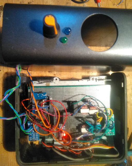
The audio strength that activates the designed vox circuit must be calibrated, such that a potentiometer is added on the outside of the case that helps adjust the required level for the audio signal to trigger the sound detection circuit. Similarly, two LEDs are drawn from both the microphone sensor PCB and the WEMOS ESP.
In practice, the microphone sensor LED is drawn to the exterior of the casing by desoldering the trigger LED on the microphone sensor (a daunting task due to the small size of the PCB). On the other hand the WEMOS LED is just activated by a GPIO pin with a resistor in series. Thus, the green LED corresponds to the microphone sensor being triggered by audio input while the blue LED will light up when the device is broadcasting (WEMOS pulls PTT low).
For the next step, one of the goals is to gradually start removing the wires by creating the circuit on the underside of the PCB. Every connection, aside the connections to and from the ESP, that is made using a wire, should be migrated to a circuit on the bottom part of the PCB. The ESP connections will retain the wiring in order to be able to swap GPIO ports, if needed. This also implies that the connection from the microphone sensor to the ESP will still be made using a cable.
Additionally some power leads can be added to the build in order to be able to connect the injector to a transformer directly without needing a power jack. Some two-part Bison epoxy is used to create a seal through which the power wires are pulled out.
Comparing to Other Hardware
One thing to pay attention to is the purity of the spectra generated by the audio injector. For instance, given a Yaesu SCU-17 audio injector, just connecting the audio injector to the USB port of the computer and then looking at the waterfall distribution of the input audio channel, the following sectra is to be observed:
Albeit surprising, it seems that the Yaesu SCU-17 is extremely noisy. Lower frequencies up to  are completely polluted, there is solid and consistent noise in the
  bands as well as some other solid noise about
  . Additionally, it seems that the whole spectra is polluted with various noise being perceived at various frequency intervals.
Repeating the experiment with the device detailed on this page, the following frequency distribution is to be observed:
As can be observed, there is some solid noise around  , and more than likely this will be solved when the wires are replaced by straight connections, but other than that the spectra is very pure. Even on the low frequency range
  , there is barely any noise. Even though the Yaesu SCU-17 claims to have full isolation of the audio circuitry, one can only guess that the noise might be due to the SCU-17 being powered from the USB port whereas the device created by us isolates the VOX coupling circuit from the sound card. Even so, the results are surprising.
Using WSJT-X and clearing up some of the noise of the device by creating solid copper connections instead of using Dupont wires, the following waterfall display is achieved with very little noise by comparison to the Yaesu SCU-17.
The emphasized horizontal lines around  are the result of a CQ call from a HAM radio operator. Other than that, the whole frequency range seems very clean.
Redesign, Rebuild and Remake
The following section describes the next version of the vox sound input device that was built in order to address some of the shortcomings of the current design. In essence, it is the result of the QA process of having used the device across a time-span of roughly a year.
Errata
The following list should summarize the currently detected flaws of the build:
- the device is just too large; whilst it is convenient to build within large enclosures due to plenty of clearance, the extra space reduces the portability of the device,
- the solid state relay does not seem to work so well, and a mechanical relay should work better,
- the input and output stereo jacks that have been mounted as an adagio to the back of the device are not really necessary and have never been used,
- the complexity of operating the device could be significantly reduced, and the device could perhaps be operated remotely; adjusting the potentiometer seems to be vital given different signal levels, such that a digital potentiometer could be used instead along with a remote control and thereby eliminate the need for the device to be close to the radio,
- it feels annoying to have to dismantle the whole case in order to retrieve the ESP and then to reprogram it; in the meanwhile, the preboot WiFi environment has been developed, such that the ESP could be programmed with the template in order to enable OTA and also have the extra benefit of being able to conveniently reconnect to the WiFi network
Changes
After about one year of usage, the audio injector has proven itself fabulous being much better performing than an official Yaesu audio injector and also much better performing than the DigiKey that interestingly has a much worse spectre in terms of noise than the Wizardry and Steamworks audio injector. However, it just seems that the injector is a little too large given that initially the project thought to include other features that were then deemed not be necessary or even detrimental to the injector such as an LCD screen with a spectrogram rendering. It was about time to create a new design of the audio injector that preserves the same technology and with the hopes of minimizing the overall build that is way too bulky.
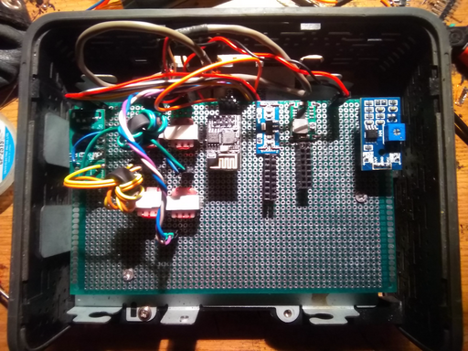
The new rebuild that was created is housed within an aluminum cage, that also provides some additional EMI protection due to implicitly creating a Farraday cage around the circuitry. The circuitry itself, remains the same, just that the potentiometer at the front of the old build became annoying to reach, and more than often the injector had to be placed on the desk, next to the operator, such that the new build incorporated a double-relay device with a remote control with which the VOX latch level can be adjusted. The same latch-relay has been used to create an ATAS-120 antenna controller such that we had some experience with using these devices and, they are so nice, so small and so easy to integrate within any circuit, that we'd buy an entire truckload of these small devices if we could. The full build is not pictured because much of the construction would be redundant given that this is just a remake with a twist, however here is the a top-side view of the device and its components.
Interestingly enough, this has been a difficult build, with the components squeezed tightly among each other with little space for anything else. The bottom side of the PCB contains the entire circuit traces that have been designed as the previous build using rigid copper wires and it is about the same procedure that is done for every one of our builds. As usual, all the key-components are socketed, such that the ESP8266, the digital potentiometer, the microphone sensor and the miniature remote double-relay can just be removed and replaced or repurposed if need be. The build is also centered around an ESP8266 that is the main controller implementing the various functions of the audio injector.
The soundcard is contained within the metal / aluminum shield on the left that is connected via leads to the device. The metal shield adds an additional layer of EMI protection by wrapping the sound card in a second internal Faraday cage. Albeit difficult to observe, just underneath the aluminum cage, the two 1:1 audio transformers can be observed, both of them providing a "galvanic"-free connection between the sound card and the Yaesu radio audio input and output in order to prevent any sort of backdraft EMI feedback from the radio for a flawless spectre. The following image is the soundcard wrapped first in rubber, then placed within aluminum plates all around, held together with hot-melt plastic glue and the USB leads on the right of the image and the audio leads on the left of the image (input and output).
As can be seen from the image, on the upper left there are two JST headers that connect to a PCB that seems to be oriented vertically. This is actually a good trick to obtain more space to place components. If a PCB shim is filed down just to the margin of the solder holes on the PCB, then the PCB shim can be elegantly soldered on top of a different PCB. Using this trick you can create multi-layered and 3D oriented circuitry, mostly for the purpose of gaining space or placing components away from each other.
Compared to the previous build that used a manual potentiometer, the remote double-relay is used to adjust the sensitivity; this is done by reading the relays in order to adjust the sensitivity of the microphone sensor, and that function, in turn, is performed by using the ESP8266 to control an X9C* digital potentiometer. The X9C* series of potentiometers can be controlled using a three-wire protocol in order to set a state from 1 to 100 that represent resistor values on a linear scale between the limits of the particular potentiometer being used - in this case, the X9C103 model was used that ranges between  and
and  . It should be noted that for some reason these potentiometers are fairly expensive relative to the other components but well-worth the enjoyment of being able to remotely adjust a dial, given that these potentiometers could be used to automate any sort of dial on right about any device that uses a manual varistor for various settings.
Another feature of the new redesign / remake has been that instead of using a pre-made step-down buck converter, an LM7805 
 power regulator.
The LM7805 is bulky and powerful enough to be likely to transfer  such that it makes good choice for power-hardware that matches the Yaesu's capabilities. The circuit presented is easy to implement and just uses two capacitors to minimize ripple across the circuit.
The code itself does not change too much, and, in fact, some of the older paradigms have been ported over, such as the usage of the TickTwo timer. Nevertheless, the sketch remains just as simple and the only novelty is the addition of the code meant to control the digital potentiometer in order to adjust the sensitivity level of the microphone sensor.
The final result is equally swell as the older design, with some quality of life features added and definitely much less bulky than the original version. Similarly, the new injector design also presents a better spectra than the other injectors that have been tested (Yaesu and DigiKey) as well as now having an aluminium enclosure that even protects from physical shocks.
It was a laborious build, but it works great!
Code
The code uses the WiFi preboot template to ensure connectivity to a WiFi network in order to be able to update the template via Arduino OTA. No worries, if the template is not connected to any STA AP, the template is still able to perform its main function for mobile operation scenarios.
One highlight is the usage of the "TickTwo" library (in principle, using milis() and measuring time to only run code when it is scheduled) that allows code to be scheduled when needed via timers in order to ensure that the "virtual thread" that is reading the digital output of the microphone sensor runs at a higher resolution than the rest of the code. This is necessary because the digital output of the microphone emits spurious zero-level signals when audio is perceived and the template is made to debounce the PTT key (similar to alarm(5) in systems programming) after some defined time has elapsed. By running at a higher priority, the template ensures that the timeout can be increased by collecting more zero-level signals than at a lower resolution.
///////////////////////////////////////////////////////////////////////////
//  Copyright (C) Wizardry and Steamworks 2024 - License: GNU MIT        //
//  Please see: http://www.gnu.org/licenses/gpl.html for legal details,  //
//  rights of fair usage, the disclaimer and warranty conditions.        //
///////////////////////////////////////////////////////////////////////////
// This is a template for a HAM radio audio injector that has been       //
// designed by Wizardry and Steamworks. The full documentation of the    //
// injector can be found on:                                             //
//   * https://grimore.org/ham_radio/                                    //
//         designing_a_vox_sound_input_for_ham_radios                    //
// where the electronic component can be found as well.                  //
///////////////////////////////////////////////////////////////////////////

///////////////////////////////////////////////////////////////////////////
//  configurable parameters                                              //
///////////////////////////////////////////////////////////////////////////

// comment out to enable debugging
//#define DEBUG 1

// set the master password for OTA updates and access to the soft AP
#define PREBOOT_MASTER_PASSWORD ""

// the name and length of the cookie to use for authentication
#define PREBOOT_COOKIE_NAME "ArduinoPrebootCookie"
#define PREBOOT_COOKIE_MAX_LENGTH 256

// timeout to establish STA connection in milliseconds
#define WIFI_RETRY_TIMEOUT 1000 * 10

// retries as multiples of WIFI_RETRY_TIMEOUT milliseconds
#define WIFI_CONNECT_TRIES 60

// how much time to wait for a client to reconfigure before switching to client mode again
#define WIFI_SERVER_TIMEOUT 1000 * 60 * 3

// the time between blinking a single digit
#define BLINK_DIT_LENGTH 250

// the time between blinking the whole number
#define BLINK_DAH_LENGTH 2500

// timeout after no signal after which PTT is closed.
#define VOX_TIMEOUT 2000

// event loop resolution
#define MICROPHONE_EVENT_RESOLUTION 25

// HAM injector parameters.
#if defined(ARDUINO_ARCH_ESP8266)
#define MICROPHONE_GPIO D0
#define DAKY_GPIO D8
#elif defined(ARDUINO_ARCH_ESP32)
#define MICROPHONE_GPIO 5
#define DAKY_GPIO 3
#endif

// potentiometer value thresholds.
#define DOWN_LOW 700
#define DOWN_HIGH 1000
#define UP_LOW 1000
#define UP_HIGH 1025

///////////////////////////////////////////////////////////////////////////
//  includes                                                             //
///////////////////////////////////////////////////////////////////////////
#include <DNSServer.h>
#if defined(ARDUINO_ARCH_ESP32)
#include <WiFi.h>
#include "esp_mac.h"
#include <WebServer.h>
#include <ESPmDNS.h>
#elif defined(ESP8266)
#include <ESP8266WiFi.h>
#include <ESP8266mDNS.h>
#include <ESP8266WebServer.h>
#endif

#include <FS.h>
#include <LittleFS.h>
#include <ArduinoJson.h>
// Arduino OTA
#include <WiFiUdp.h>
#include <ArduinoOTA.h>
#include <TickTwo.h>

// HAM audio injector application
#include <DigiPotX9Cxxx.h>

// Platform specific defines.
#if defined(ARDUINO_ARCH_ESP8266)
#define GET_CHIP_ID() (ESP.getChipId())
#elif defined(ARDUINO_ARCH_ESP32)
#define GET_CHIP_ID() ((uint16_t)(ESP.getEfuseMac() >> 32))
#endif

#define HOSTNAME() String("esp-" + String(GET_CHIP_ID(), HEX))
#define CONFIGURATION_FILE_NAME "/config.json"
#define CONFIGURATION_MAX_LENGTH 1024

///////////////////////////////////////////////////////////////////////////
//  function definitions                                                 //
///////////////////////////////////////////////////////////////////////////
byte* getHardwareAddress(void);
char* getHardwareAddress(char colon);
String generateTemporarySSID(void);
void arduinoOtaTickCallback(void);
void blinkDigitsDahTickCallback(void);
void blinkDigitsDitTickCallback(void);
void blinkDigitsBlinkTickCallback(void);
void clientWifiTickCallback(void);
void serverWifiTickCallback(void);
void handleServerWifi(void);
void handleClientWifi(void);

bool setConfiguration(const char* configurationFile, JsonDocument& configuration);
int getConfiguration(const char* configurationFile, JsonDocument& configuration);

void handleRootHttpRequest(void);
void handleRootCssRequest(void);
void handleSetupHttpRequest(void);
void handleRootHttpGet(void);
void handleSetupHttpGet(void);
void handleRootHttpPost(void);
void handleSetupHttpPost(void);
void handleHttpNotFound(void);

void rebootTickCallback(void);

// HAM audio injector
void microphoneTimeoutTickCallback(void);
void remoteControlTickCallback(void);
void microphoneTickCallback(void);

///////////////////////////////////////////////////////////////////////////
//  variable declarations                                                //
///////////////////////////////////////////////////////////////////////////
IPAddress softAPAddress(8, 8, 8, 8);
IPAddress softAPNetmask(255, 255, 255, 0);

DNSServer dnsServer;
#if defined(ARDUINO_ARCH_ESP8266)
ESP8266WebServer server(80);
#elif defined(ARDUINO_ARCH_ESP32)
WebServer server(80);
#endif

TickTwo arduinoOtaTick(arduinoOtaTickCallback, 1000);
TickTwo rebootTick(rebootTickCallback, 1000);
TickTwo clientWifiTick(clientWifiTickCallback, 250);
TickTwo serverWifiTick(serverWifiTickCallback, 250);
TickTwo blinkDigitsDahTick(blinkDigitsDahTickCallback, BLINK_DAH_LENGTH);
TickTwo blinkDigitsDitTick(blinkDigitsDitTickCallback, BLINK_DIT_LENGTH);
TickTwo blinkDigitsBlinkTick(blinkDigitsBlinkTickCallback, 25);

enum bootMode : int {
  BOOT_MODE_NONE = 0,
  BOOT_MODE_CLIENT,
  BOOT_MODE_SERVER
};
char* authenticationCookie = NULL;
bool otaStarted;
bool otaInProgress;
bool networkConnected;
int clientConnectionTries;
bool rebootPending;
int temporarySSIDLength;
int temporarySSIDIndex;
int* temporarySSIDNumbers;
int blinkLedState;
bool discoveryStarted;

// HAM audio injector application
// pins in sequence: INC, U/D, CS
#if defined(ARDUINO_ARCH_ESP8266)
DigiPot microphonePotentiometer(D3, D1, D2);
#elif defined(ARDUINO_ARCH_ESP32)
DigiPot microphonePotentiometer(12, 8, 3);
#endif

// HAM audio injector application
TickTwo microphoneTimeoutTick(microphoneTimeoutTickCallback, 0, 1, MILLIS);
TickTwo remoteControlTick(remoteControlTickCallback, 250);
TickTwo microphoneTick(microphoneTickCallback, MICROPHONE_EVENT_RESOLUTION);

// HAM audio injector application
bool transmitting;

///////////////////////////////////////////////////////////////////////////
//  HTML & CSS templates                                                 //
///////////////////////////////////////////////////////////////////////////
const char* GENERIC_CSS_TEMPLATE = R"html(
* {
  box-sizing: border-box;
}
body {
  background-color: #3498db;
  font-family: "Arial", sans-serif;
  padding: 50px;
}
.container {
  margin: 20px auto;
  padding: 10px;
  width: 300px;
  height: 100%;
  background-color: #fff;
  border-radius: 5px;
  margin-left: auto;
  margin-right: auto;
}
h1 {
  width: 70%;
  color: #777;
  font-size: 32px;
  margin: 28px auto;
  text-align: center;
}
form {
  text-align: center;
}
input {
  padding: 12px 0;
  margin-bottom: 10px;
  border-radius: 3px;
  border: 2px solid transparent;
  text-align: center;
  width: 90%;
  font-size: 16px;
  transition: border 0.2s, background-color 0.2s;
}
form .field {
  background-color: #ecf0f1;
}
form .field:focus {
  border: 2px solid #3498db;
}
form .btn {
  background-color: #3498db;
  color: #fff;
  line-height: 25px;
  cursor: pointer;
}
form .btn:hover,
form .btn:active {
  background-color: #1f78b4;
  border: 2px solid #1f78b4;
}
.pass-link {
  text-align: center;
}
.pass-link a:link,
.pass-link a:visited {
  font-size: 12px;
  color: #777;
}
table {
  border: 1px solid #dededf;
  border-collapse: collapse;
  border-spacing: 1px;
  margin-left: auto;
  margin-right: auto;
  width: 80%;
}
td {
  border: 1px solid #dededf;
  background-color: #ffffff;
  color: #000000;
  padding: 1em;
}
)html";

const char* HTML_SETUP_TEMPLATE = R"html(
<!DOCTYPE html>
<html lang="en">
  <head>
    <title>setup</title>
    <link rel="stylesheet" href="/style.css">
  </head>
  <body>
    <div class="container">
      <h1>setup</h1>
      <table>
        <tr>
          <td>AP</td>
          <td>%AP%</td>
        </tr>
        <tr>
          <td>MAC</td>
          <td>%MAC%</td>
        </tr>
      </table>
      <br>
      <form method="POST" action="/setup">
        <label for="name">Name</label>
        <input id="name" type="text" name="name" value="%NAME%" class="field">
        <label for="Ssid">SSID</label>
        <input id="Ssid" type="text" name="Ssid" class="field">
        <label for="password">Password</label>
        <input id="password" type="password" name="password" class="field">
        <input type="submit" value="login" class="btn">
      </form>
    </div>
  </body>
</html>
)html";

const char* HTML_AUTH_TEMPLATE = R"html(
<!DOCTYPE html>
<html lang="en">
  <head>
    <title>Preboot Access</title>
    <link rel="stylesheet" href="/style.css">
  </head>
  <body>
    <div class="container">
      <h1>admin</h1>
      <form method="POST">
        <input id="password" type="password" name="password" class="field" placeholder="password">
        <input type="submit" value="login" class="btn">
      </form>
    </div>
  </body>
</html>
)html";

///////////////////////////////////////////////////////////////////////////
//  begin Arduino                                                        //
///////////////////////////////////////////////////////////////////////////
void setup() {
#ifdef DEBUG
  Serial.begin(115200);
  // wait for serial
  while (!Serial) {
    delay(100);
  }

  Serial.println();
#else
  Serial.end();
#endif

#ifdef DEBUG
  Serial.println("Mounting filesystem...");
#endif
#if defined(ARDUINO_ARCH_ESP8266)
  if (!LittleFS.begin()) {
#ifdef DEBUG
    Serial.println("LittleFS mount failed, formatting and rebooting...");
#endif
    LittleFS.format();
    delay(1000);
    ESP.restart();
#elif defined(ARDUINO_ARCH_ESP32)
  if (!LittleFS.begin(true)) {
#endif
#ifdef DEBUG
    Serial.println("LittleFS mount & format failed...");
#endif
    return;
  }

#ifdef DEBUG
  Serial.printf("Checking if WiFi server must be started...\n");
#endif
  // check if Ssid is set and start soft AP or STA mode
  DynamicJsonDocument configuration(CONFIGURATION_MAX_LENGTH);
  if(getConfiguration(CONFIGURATION_FILE_NAME, configuration) == -1) {
#ifdef DEBUG
    Serial.println("Unable to retrieve configuration.");
#endif
    delay(60000);
    ESP.restart();
    return;
  }

  switch(configuration["boot"].as<int>()) {
    case BOOT_MODE_CLIENT:
#ifdef DEBUG
      Serial.printf("Client connecting to WiFi...\n");
#endif
      clientWifiTick.start();
      break;
    case BOOT_MODE_SERVER:
    case BOOT_MODE_NONE:
#ifdef DEBUG
      Serial.printf("Server AP starting...\n");
#endif
      // start soft AP
      rebootTick.start();
      serverWifiTick.start();
      break;
  }

  // setup OTA
  ArduinoOTA.setHostname(configuration["name"].as<const char*>());
  // allow flashing with the master password
  ArduinoOTA.setPassword(PREBOOT_MASTER_PASSWORD);
  ArduinoOTA.onStart([]() {
    // mark OTA as started
    otaInProgress = true;

    // stop LittleFS as per the documentation
    LittleFS.end();

    String type;
    if (ArduinoOTA.getCommand() == U_FLASH) {
      type = "sketch";
    } else {  // U_FS
      type = "filesystem";
    }

    // NOTE: if updating FS this would be the place to unmount FS using FS.end()
#ifdef DEBUG
    Serial.println("Start updating " + type);
#endif
  });
  ArduinoOTA.onEnd([]() {
    otaInProgress = false;
#ifdef DEBUG
    Serial.println("\nEnd");
#endif
    // restart the device
#ifdef DEBUG
    Serial.printf("Restarting ESP.\n");
#endif
    delay(1000);
    ESP.restart();
  });
  ArduinoOTA.onProgress([](unsigned int progress, unsigned int total) {
#ifdef DEBUG
    Serial.printf("Progress: %u%%\r", (progress / (total / 100)));
#endif
  });
  ArduinoOTA.onError([](ota_error_t error) {
#ifdef DEBUG
    Serial.printf("Error[%u]: ", error);
#endif
    if (error == OTA_AUTH_ERROR) {
#ifdef DEBUG
      Serial.println("Auth Failed");
#endif
    } else if (error == OTA_BEGIN_ERROR) {
#ifdef DEBUG
      Serial.println("Begin Failed");
#endif
    } else if (error == OTA_CONNECT_ERROR) {
#ifdef DEBUG
      Serial.println("Connect Failed");
#endif
    } else if (error == OTA_RECEIVE_ERROR) {
#ifdef DEBUG
      Serial.println("Receive Failed");
#endif
    } else if (error == OTA_END_ERROR) {
#ifdef DEBUG
      Serial.println("End Failed");
#endif
    }
  });

  // start timers / threads
  arduinoOtaTick.start();
  rebootTick.start();

  // HAM audio injector application
  pinMode(MICROPHONE_GPIO, INPUT);
  pinMode(DAKY_GPIO, OUTPUT);
  remoteControlTick.start();
  microphoneTick.start();
}

void loop() {
  arduinoOtaTick.update();
  rebootTick.update();
  clientWifiTick.update();
  serverWifiTick.update();
  blinkDigitsDitTick.update();
  blinkDigitsDahTick.update();
  blinkDigitsBlinkTick.update();

  // HAM audio injector application
  remoteControlTick.update();
  microphoneTick.update();
  microphoneTimeoutTick.update();
}

///////////////////////////////////////////////////////////////////////////
//  end Arduino                                                          //
///////////////////////////////////////////////////////////////////////////

///////////////////////////////////////////////////////////////////////////
//  HAM audio injector                                                   //
///////////////////////////////////////////////////////////////////////////
void microphoneTickCallback(void) {
  if (!digitalRead(MICROPHONE_GPIO)) {
    switch (transmitting) {
      case true:
#ifdef DEBUG
        Serial.print(".");
#endif
        microphoneTimeoutTick.interval(VOX_TIMEOUT + MICROPHONE_EVENT_RESOLUTION);
        microphoneTimeoutTick.resume();
        break;
      case false:
#ifdef DEBUG
        Serial.print("PTT: ");
#endif
        digitalWrite(DAKY_GPIO, HIGH);
        microphoneTimeoutTick.interval(VOX_TIMEOUT + MICROPHONE_EVENT_RESOLUTION);
        microphoneTimeoutTick.resume();
        transmitting = true;
        break;
    }
  }
}

void microphoneTimeoutTickCallback(void) {
  // deactivate PTT transistor switch / PTT low (start broadcast)
#ifdef DEBUG
  Serial.println("✓");
#endif
  microphoneTimeoutTick.pause();
  digitalWrite(DAKY_GPIO, LOW);
  transmitting = false;
}

void remoteControlTickCallback(void) {
  // process remote control and adjust potentiometer
  int remote = analogRead(A0);
  if (DOWN_LOW < remote && remote < DOWN_HIGH) {
#ifdef DEBUG
    Serial.printf("microphone sensitivity ↓\n");
#endif
    microphonePotentiometer.decrease(1);
    return;
  }

  if (UP_LOW < remote && remote < UP_HIGH) {
#ifdef DEBUG
    Serial.printf("microphone sensitivity ↑\n");
#endif
    microphonePotentiometer.increase(1);
  }
}

///////////////////////////////////////////////////////////////////////////
//  OTA updates                                                          //
///////////////////////////////////////////////////////////////////////////
void arduinoOtaTickCallback(void) {
  ArduinoOTA.handle();

  if(!networkConnected) {
    return;
  }

  if(!otaStarted) {
    ArduinoOTA.begin();
    otaStarted = true;
  }
}

///////////////////////////////////////////////////////////////////////////
//  system-wide reboot                                                   //
///////////////////////////////////////////////////////////////////////////
void rebootTickCallback(void) {
  // if not reboot hasbeen scheduled then just return
  if(!rebootPending) {
    return;
  }

#ifdef DEBUG
  Serial.printf("Stopping filesystem...\n");
#endif
#ifdef DEBUG
  LittleFS.end();
#endif
#ifdef DEBUG
  Serial.printf("Rebooting...\n");
#endif
  ESP.restart();
}

///////////////////////////////////////////////////////////////////////////
//  HTTP route handling                                                  //
///////////////////////////////////////////////////////////////////////////
void handleRootHttpPost(void) {
  String password;
  for(int i = 0; i < server.args(); ++i) {
    if(server.argName(i) == "password") {
      password = server.arg(i);
      continue;
    }
  }

  if(!password.equals(PREBOOT_MASTER_PASSWORD)) {
    server.sendHeader("Location", "/");
    server.sendHeader("Cache-Control", "no-cache");
    server.send(302);
    return;
  }

#ifdef DEBUG
  Serial.println("Authentication succeeded, setting cookie and redirecting.");
#endif

  // clear old authentication cookie
  if(authenticationCookie != NULL) {
    free(authenticationCookie);
    authenticationCookie = NULL;
  }

  authenticationCookie = randomStringHex(8);
  char* buff = (char*) malloc(PREBOOT_COOKIE_MAX_LENGTH * sizeof(char));
  snprintf(buff, PREBOOT_COOKIE_MAX_LENGTH, "%s=%s; Max-Age=600; SameSite=Strict", PREBOOT_COOKIE_NAME, authenticationCookie);
#ifdef DEBUG
  Serial.printf("Preboot cookie set to: %s\n", buff);
#endif
  server.sendHeader("Set-Cookie", buff);
  server.sendHeader("Location", "/setup");
  server.sendHeader("Cache-Control", "no-cache");
  server.send(302);
  free(buff);
}

void handleSetupHttpPost(void) {
  String espName, staSsid, password;
  for(int i = 0; i < server.args(); ++i) {
    if(server.argName(i) == "name") {
      espName = server.arg(i);
      continue;
    }

    if(server.argName(i) == "Ssid") {
      staSsid = server.arg(i);
      continue;
    }

    if(server.argName(i) == "password") {
      password = server.arg(i);
      continue;
    }
  }

  if(espName == NULL || staSsid == NULL || password == NULL) {
      server.sendHeader("Location", "/");
      server.sendHeader("Cache-Control", "no-cache");
      server.send(302);
      return;
  }

#ifdef DEBUG
  Serial.printf("Ssid %s and password %s received from web application.\n", staSsid, password);
#endif
  DynamicJsonDocument configuration(CONFIGURATION_MAX_LENGTH);
  configuration["name"] = espName;
  configuration["Ssid"] = staSsid;
  configuration["password"] = password;
  configuration["boot"] = BOOT_MODE_CLIENT;
  if(!setConfiguration(CONFIGURATION_FILE_NAME, configuration)) {
#ifdef DEBUG
    Serial.printf("Failed to write configuration.\n");
#endif
    server.sendHeader("Location", "/setup");
    server.sendHeader("Cache-Control", "no-cache");
    server.send(307);
    return;
  }

  server.send(200, "text/plain", "Parameters applied. Scheduling reboot...");

#ifdef DEBUG
  Serial.printf("Configuration applied...\n");
#endif

  rebootPending = true;
}

void handleRootHttpGet(void) {
  // send login form
#ifdef DEBUG
  Serial.printf("Sending authentication webpage.\n");
#endif
  String processTemplate = String(HTML_AUTH_TEMPLATE);
  server.send(200, "text/html", processTemplate);
}

void handleSetupHttpGet(void) {
  DynamicJsonDocument configuration(CONFIGURATION_MAX_LENGTH);
  if(getConfiguration(CONFIGURATION_FILE_NAME, configuration) == -1) {
#ifdef DEBUG
    Serial.println("Unable to retrieve configuration.");
#endif
    server.sendHeader("Location", "/setup");
    server.sendHeader("Cache-Control", "no-cache");
    server.send(307);
  }

  String espName = HOSTNAME();
  if(configuration.containsKey("name")) {
    espName = configuration["name"].as<const char*>();
  }
  // send default boot webpage
#ifdef DEBUG
  Serial.printf("Sending configuration form webpage.\n");
#endif
  String processTemplate = String(HTML_SETUP_TEMPLATE);
  processTemplate.replace("%AP%", generateTemporarySSID());
  processTemplate.replace("%MAC%", getHardwareAddress(':'));
  processTemplate.replace("%NAME%", espName);
  server.send(200, "text/html", processTemplate);
}

void handleRootHttpRequest(void) {
  switch(server.method()) {
    case HTTP_GET:
      handleRootHttpGet();
      break;
    case HTTP_POST:
      handleRootHttpPost();
      break;
  }
}

void handleRootCssRequest(void) {
  if(server.method() != HTTP_GET) {
    handleHttpNotFound();
    return;
  }

#ifdef DEBUG
  Serial.println("Sending stylesheet...");
#endif
  String rootCss = String(GENERIC_CSS_TEMPLATE);
  server.send(200, "text/css", rootCss);
}

void handleSetupHttpRequest(void) {
#ifdef DEBUG
  Serial.println("HTTP setup request received.");
#endif
  if(!server.hasHeader("Cookie")) {
#ifdef DEBUG
    Serial.println("No cookie header found.");
#endif
    server.sendHeader("Location", "/");
    server.sendHeader("Cache-Control", "no-cache");
    server.send(302);
    return;
  }

  String cookie = server.header("Cookie");
  if(authenticationCookie == NULL || cookie.indexOf(authenticationCookie) == -1) {
#ifdef DEBUG
    Serial.println("Authentication failed.");
#endif
    server.sendHeader("Location", "/");
    server.sendHeader("Cache-Control", "no-cache");
    server.send(302);
    return;
  }

  switch(server.method()) {
    case HTTP_GET:
#ifdef DEBUG
      Serial.printf("HTTP GET request received for setup.\n");
#endif
      handleSetupHttpGet();
      break;
    case HTTP_POST:
#ifdef DEBUG
      Serial.printf("HTTP POST request received for setup.\n");
#endif
      handleSetupHttpPost();
      break;
  }
}

void handleHttpNotFound(void) {
  server.sendHeader("Cache-Control", "no-cache");
  server.send(404);
}

///////////////////////////////////////////////////////////////////////////
//  set the current configuration                                        //
///////////////////////////////////////////////////////////////////////////
bool setConfiguration(const char* configurationFile, JsonDocument& configuration) {
#if defined(ARDUINO_ARCH_ESP8266)
  File file = LittleFS.open(configurationFile, "w");
#elif defined(ARDUINO_ARCH_ESP32)
  File file = LittleFS.open(configurationFile, FILE_WRITE);
#endif
  if(!file) {
#ifdef DEBUG
    Serial.println("Failed to open file for writing.");
#endif
    return false;
  }
  size_t bytesWritten = serializeJson(configuration, file);
  file.close();
#ifdef DEBUG
  Serial.printf("Written bytes %d vs. document bytes %d\n", bytesWritten, measureJson(configuration));
#endif
  return bytesWritten == measureJson(configuration);
}

///////////////////////////////////////////////////////////////////////////
//  get the current configuration                                        //
///////////////////////////////////////////////////////////////////////////
int getConfiguration(const char* configurationFile, JsonDocument& configuration) {
#if defined(ARDUINO_ARCH_ESP8266)
  File file = LittleFS.open(configurationFile, "r");
#elif defined(ARDUINO_ARCH_ESP32)
  File file = LittleFS.open(configurationFile);
#endif

  if (!file) {
#ifdef DEBUG
    Serial.println("Failed to open file for reading.");
#endif
    return false;
  }

  DeserializationError error = deserializeJson(configuration, file);
  file.close();
  if(error) {
#ifdef DEBUG
    Serial.printf("Deserialization failed with error %s\n", error.c_str());
#endif
    return -1;
  }

  return measureJson(configuration);
}

///////////////////////////////////////////////////////////////////////////
//  generate random string                                               //
///////////////////////////////////////////////////////////////////////////
char* randomStringHex(int length) {
  const char alphabet[] = "0123456789abcdef";
  char* payload = (char*) malloc(length * sizeof(char));
  int i;
  for (i=0; i<length; ++i) {
    payload[i] = alphabet[random(16)];
  }
  payload[i] = '\0';
  return payload;
}

///////////////////////////////////////////////////////////////////////////
//  get wireless status                                                  //
///////////////////////////////////////////////////////////////////////////
const char* wl_status_to_string(wl_status_t status) {
  switch (status) {
    case WL_NO_SHIELD: return "WL_NO_SHIELD";
    case WL_IDLE_STATUS: return "WL_IDLE_STATUS";
    case WL_NO_SSID_AVAIL: return "WL_NO_SSID_AVAIL";
    case WL_SCAN_COMPLETED: return "WL_SCAN_COMPLETED";
    case WL_CONNECTED: return "WL_CONNECTED";
    case WL_CONNECT_FAILED: return "WL_CONNECT_FAILED";
    case WL_CONNECTION_LOST: return "WL_CONNECTION_LOST";
    case WL_DISCONNECTED: return "WL_DISCONNECTED";
#if defined(ARDUINO_ARCH_ESP32)
    case WL_STOPPED: return "WL_STOPPED";
#endif
  }

  return "UNKNOWN";
}

///////////////////////////////////////////////////////////////////////////
//  get WiFi MAC address                                                 //
///////////////////////////////////////////////////////////////////////////
byte* getHardwareAddress(void) {
  // get mac address
  byte* mac = (byte *)malloc(6 * sizeof(byte));
#if defined(ARDUINO_ARCH_ESP8266)
  WiFi.macAddress(mac);
#elif defined(ARDUINO_ARCH_ESP32)
  esp_read_mac(mac, ESP_MAC_WIFI_STA);
#endif
  return mac;
}

///////////////////////////////////////////////////////////////////////////
//  convert MAC address to string                                        //
///////////////////////////////////////////////////////////////////////////
char* getHardwareAddress(char colon) {
  byte* mac = getHardwareAddress();
  char* buff = (char *)malloc(18 * sizeof(char));
  sprintf(buff, "%02x%c%02x%c%02x%c%02x%c%02x%c%02x",
    mac[0],
    colon,
    mac[1],
    colon,
    mac[2],
    colon,
    mac[3],
    colon,
    mac[4],
    colon,
    mac[5]
  );

  free(mac);
  return buff;
}

///////////////////////////////////////////////////////////////////////////
//  get WiFi soft AP                                                     //
///////////////////////////////////////////////////////////////////////////
String generateTemporarySSID(void) {
  byte* mac = getHardwareAddress();
  String ssid = String(mac[0] ^ mac[1] ^ mac[2] ^ mac[3] ^ mac[4] ^ mac[5], DEC);
  free(mac);
  return ssid;
}

///////////////////////////////////////////////////////////////////////////
//  serve WiFi AP                                                        //
///////////////////////////////////////////////////////////////////////////
void serverWifiTickCallback(void) {
  if(rebootPending || otaInProgress) {
    return;
  }

  // when a certain number of ticks have elapsed boot again to client mode
  // in order to retry the existing credentials in case the AP recovered
  unsigned long callbackTickTime = serverWifiTick.counter() * (serverWifiTick.interval() / 1000);
  if(callbackTickTime >= WIFI_SERVER_TIMEOUT) {
#ifdef DEBUG
    Serial.println("Server timeout, rebooting...\n");
#endif

    // retrieve the configuration so we do not end up overwriting the old client settings
    DynamicJsonDocument configuration(CONFIGURATION_MAX_LENGTH);
    if(getConfiguration(CONFIGURATION_FILE_NAME, configuration) == -1) {
       // if the configuration could not be retrieved then just reboot
#ifdef DEBUG
        Serial.println("Unable to retrieve configuration.");
#endif
        rebootPending = true;
        return;
    }

    // reboot to client mode in order to retry the connection
    configuration["boot"] = BOOT_MODE_CLIENT;
    if(!setConfiguration(CONFIGURATION_FILE_NAME, configuration)) {
#ifdef DEBUG
      Serial.printf("Failed to write configuration.\n");
#endif
    }

    rebootPending = true;
    return;
  }

#ifdef DEBUG
/*
  if(callbackTickTime % 1000 == 0 ) {
    Serial.printf("Time till reboot %.0fs\n", (float)(WIFI_SERVER_TIMEOUT - callbackTickTime)/1000.0);
  }
*/
#endif

  // create the boot SSID
  String temporarySSID = generateTemporarySSID();
  if(WiFi.softAPSSID().equals(temporarySSID)) {
    // run WiFi server loops
    dnsServer.processNextRequest();
    server.handleClient();
    MDNS.update();

    if(blinkDigitsDahTick.state() == STOPPED) {
      temporarySSIDLength = temporarySSID.length();
      temporarySSIDNumbers = (int *) malloc(temporarySSIDLength * sizeof(int));
      for(int i = 0; i < temporarySSIDLength; ++i) {
        temporarySSIDNumbers[i] = temporarySSID[i] - '0';
      }
      temporarySSIDIndex = 0;
      blinkDigitsDahTick.start();
    }
    return;
  }

#ifdef DEBUG
  Serial.println("Starting HTTP server for Wifi server.");
#endif
  // handle HTTP REST requests
  server.on("/", handleRootHttpRequest);
  server.on("/setup", handleSetupHttpRequest);
  server.on("/style.css", handleRootCssRequest);
  // captive portal proprietary junk redirected to webserver root
  // connectivitycheck.gstatic.com/generate_204
  // www.googe.com/gen_204
  server.on("/generate_204", handleRootHttpRequest);
  server.on("/gen_204", handleRootHttpRequest);
  server.on("/fwlink", handleRootHttpRequest);
  server.onNotFound(handleHttpNotFound);

#ifdef DEBUG
  Serial.println("Ensure HTTP headers are collected by the HTTP server.");
#endif
#if defined(ARDUINO_ARCH_ESP8266)
  server.collectHeaders("Cookie");
#elif defined(ARDUINO_ARCH_ESP32)
  const char* collectHeaders[] = { "Cookie" };
  size_t headerkeyssize = sizeof(collectHeaders) / sizeof(char *);
  server.collectHeaders(collectHeaders, headerkeyssize);
#endif

  // the soft AP (or WiFi) must be started before the HTTP server or it will result in a crash on ESP32
#ifdef DEBUG
  Serial.println("Starting temporary AP.");
#endif

  WiFi.softAPConfig(softAPAddress, softAPAddress, softAPNetmask);
  WiFi.softAP(temporarySSID, String(), 1, false, 1);
  dnsServer.setErrorReplyCode(DNSReplyCode::NoError);
  dnsServer.start(53, "*", softAPAddress);

#ifdef DEBUG
  Serial.println("Starting HTTP server.");
#endif

  if (!discoveryStarted) {
    if(!MDNS.begin(temporarySSID)) {
#ifdef DEBUG
      Serial.println("Error setting up MDNS responder.");
#endif
      return;
    }
    discoveryStarted = true;
  }

  server.begin();
}

///////////////////////////////////////////////////////////////////////////
//  connect to WiFi                                                      //
///////////////////////////////////////////////////////////////////////////
void clientWifiTickCallback(void) {
  if(rebootPending || otaInProgress) {
    return;
  }

  unsigned long callbackCount = clientWifiTick.counter();
#ifdef DEBUG
  //Serial.printf("Client tick %lu\n", callbackCount);
#endif
  if(callbackCount == 1) {
#ifdef DEBUG
    Serial.printf("Rescheduling client WiFi to check mevery 10s...\n");
#endif
    clientWifiTick.interval(WIFI_RETRY_TIMEOUT);
    clientWifiTick.resume();
  }

  // if WiFi is already connected or a reboot is pending just bail out
  wl_status_t wifiStatus = WiFi.status();
  if(wifiStatus == WL_CONNECTED) {
    if (!discoveryStarted) {
      DynamicJsonDocument configuration(CONFIGURATION_MAX_LENGTH);
      if(getConfiguration(CONFIGURATION_FILE_NAME, configuration) == -1) {
#ifdef DEBUG
        Serial.println("Unable to retrieve configuration.");
#endif
        rebootPending = true;
        return;
      }

      if(!MDNS.begin(configuration["name"].as<const char*>())) {
#ifdef DEBUG
        Serial.println("Error setting up MDNS responder.");
#endif
        return;
      }
      discoveryStarted = true;
    }
#ifdef DEBUG
    Serial.println("-- MARK --");
#endif
    clientConnectionTries = 0;
    networkConnected = true;
    MDNS.update();
    return;
  }

#ifdef DEBUG
  Serial.printf("Client WiFi not connected: %d\n", wl_status_to_string(wifiStatus));
#endif

  networkConnected = false;

  DynamicJsonDocument configuration(CONFIGURATION_MAX_LENGTH);
  if(getConfiguration(CONFIGURATION_FILE_NAME, configuration) == -1) {
#ifdef DEBUG
    Serial.println("Unable to retrieve configuration.");
#endif
    return;
  }

  // too many retries so reboot to soft AP
  if(++clientConnectionTries > WIFI_CONNECT_TRIES) {
    configuration["boot"] = BOOT_MODE_SERVER;
    if(!setConfiguration(CONFIGURATION_FILE_NAME, configuration)) {
#ifdef DEBUG
      Serial.printf("Failed to write configuration.\n");
#endif
    }

#ifdef DEBUG
    Serial.printf("Restarting in 1 second...\n");
#endif

    rebootPending = true;
    return;
  }

#ifdef DEBUG
  Serial.printf("Attempting to establish WiFi STA connecton [%d/%d]\n", (WIFI_CONNECT_TRIES - clientConnectionTries) + 1, WIFI_CONNECT_TRIES);
#endif
#if defined(ARDUINO_ARCH_ESP8266)
  WiFi.hostname(configuration["name"].as<String>());
#elif defined(ARDUINO_ARCH_ESP32)
  WiFi.setHostname(configuration["name"].as<const char*>());
#endif
  if (!MDNS.begin(configuration["name"].as<const char*>())) {
#ifdef DEBUG
    Serial.println("Error setting up MDNS responder.");
#endif
  }
  String Ssid = configuration["Ssid"].as<String>();
  String password = configuration["password"].as<String>();
#ifdef DEBUG
  Serial.printf("Trying connection to %s with %s...\n", Ssid, password);
#endif
  //WiFi.config(INADDR_NONE, INADDR_NONE, INADDR_NONE);
  WiFi.begin(Ssid, password);
}

///////////////////////////////////////////////////////////////////////////
//  blink the temporary Ssid                                             //
///////////////////////////////////////////////////////////////////////////
void blinkDigitsDahTickCallback(void) {
  // wait for the dits to complete
  if(blinkDigitsDitTick.state() != STOPPED) {
    return;
  }

  if(temporarySSIDIndex >= temporarySSIDLength) {
    blinkDigitsDahTick.stop();
    blinkDigitsDitTick.stop();
    blinkDigitsBlinkTick.stop();
    free(temporarySSIDNumbers);
#ifdef DEBUG
    Serial.println();
    Serial.println("Dah-dit blink sequence completed.");
#endif
    return;
  }

#ifdef DEBUG
  Serial.printf("Starting to blink %d times: ", temporarySSIDNumbers[temporarySSIDIndex]);
#endif

  pinMode(LED_BUILTIN, OUTPUT);
  digitalWrite(LED_BUILTIN, LOW);
  blinkDigitsDitTick.start();
}

void blinkDigitsDitTickCallback(void) {
#ifdef DEBUG
  Serial.printf("Dit: %d/%d\n", blinkDigitsDitTick.counter(), temporarySSIDNumbers[temporarySSIDIndex]);
#endif
  if(blinkDigitsDitTick.counter() > temporarySSIDNumbers[temporarySSIDIndex]) {
    blinkDigitsDitTick.stop();
    ++temporarySSIDIndex;
#ifdef DEBUG
    Serial.println("Dits completed...");
#endif
    return;
  }

  blinkDigitsDitTick.pause();
  blinkDigitsBlinkTick.start();
}

void blinkDigitsBlinkTickCallback(void) {
  if(blinkDigitsBlinkTick.counter() > 2) {
    blinkDigitsBlinkTick.stop();
    blinkDigitsDitTick.resume();
    return;
  }
  blinkLedState = !blinkLedState;
  digitalWrite(LED_BUILTIN, blinkLedState);
}
For the contact, copyright, license, warranty and privacy terms for the usage of this website please see the contact, license, privacy, copyright.
