Table of Contents
Identification
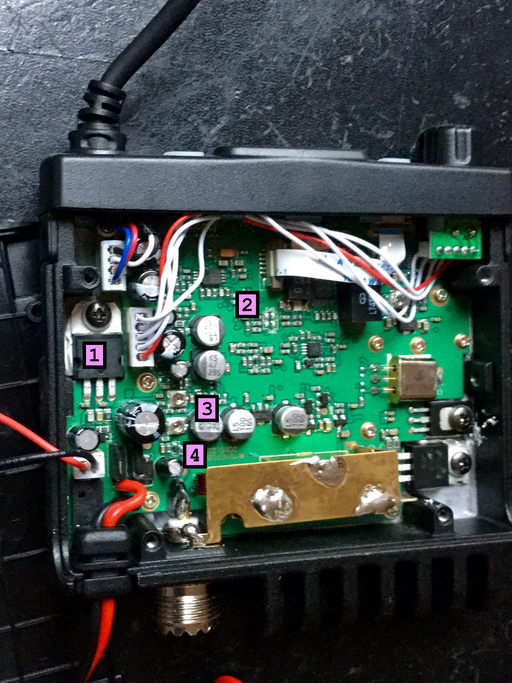
- output tranzistor, a PNP MJE2955T,
- standards adjustment pins,
- dials:
- AM/FM modulation,
- transmit power,
- modulation limiter
(1) Output Tranzistor
The audio output tranzistor is responsible with the radio transmit: in case the radio fails to transmit but can receive then most likely the tranzistor is blown and must be replaced. One common reason for blowing out the audio output tranzistor is to transmit without any antenna attached such that an antenna must be connected at all times when transmitting.
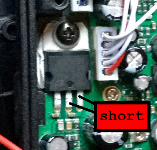
The power output of the CRT ONE can be boosted to about  in case the MJE2955T tranzistor is shortened. The result is that the power over the FM band will increase but there will be losses and distortions to the AM band. One possible modification is to add a switch in order to short the tranzistor in order to toggle between the standard power output and the high power output over the FM band. To short the tranzistor, simply connect the collector and the emitter of the MJE2955T together thereby bypassing the tranzistor mechanism altogether.
(2) Standards Adjustment
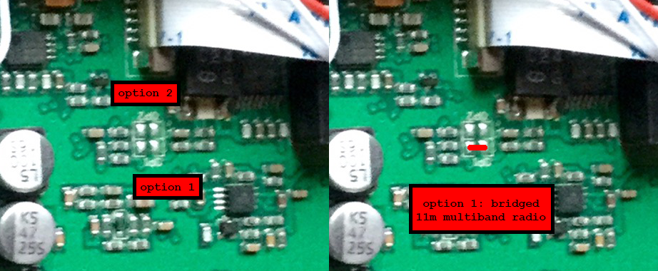
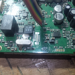
The CRT ONE is a multiband export radio, meaning that the bands are presumably adjusted before being sold on a certain market. The four solder pads on the middle of the top PCB can be used to set the standard for export.
There are three possible configurations for the CRT ONE:
- No bridge, default
| Channels | Frequency Range | Band |
|---|---|---|
| 40 | ![Math $[26.965,27.405]Mhz$](/lib/exe/fetch.php?media=wiki:latex:/imgc7521c6eda99868024de5f8e1d41a413.png) | EU (default) |
| 40 | ![Math $[26.965,27.405]Mhz$](/lib/exe/fetch.php?media=wiki:latex:/imgc7521c6eda99868024de5f8e1d41a413.png) | CE |
| 40 | ![Math $[27.60125,27.99125]Mhz$](/lib/exe/fetch.php?media=wiki:latex:/imgfbf0a4de875543b038bc973b562c9705.png) | UK |
| 40 | ![Math $[26.960,27.400]Mhz$](/lib/exe/fetch.php?media=wiki:latex:/img8b339c292211e5efbc73607c8d16fbe2.png) | PL |
| 36 | ![Math $[26.965,26.865]Mhz$](/lib/exe/fetch.php?media=wiki:latex:/imgf9bed208f30a10c62f37c61e57de6627.png) | I2 |
| 40 | ![Math $[26.965,27.405]Mhz$](/lib/exe/fetch.php?media=wiki:latex:/imgc7521c6eda99868024de5f8e1d41a413.png) | DE |
| 80 | ![Math $[26.565,26.955]Mhz$](/lib/exe/fetch.php?media=wiki:latex:/img43263b23b72812c3ec80cb77a5fb29dd.png) |
|
| 27 | ![Math $[26.965,27.275]Mhz$](/lib/exe/fetch.php?media=wiki:latex:/img031d2a26f5cadb6dd6106bc44b31c709.png) | IN |
- Option 2 bridged,
 amateur band
| Channels | Frequency Range | Band |
|---|---|---|
| 40 | ![Math $[28.000,28.195]Mhz$](/lib/exe/fetch.php?media=wiki:latex:/img4a34565ba09d8d7b5f3a24714cc7ccbf.png) | HA |
| 40 | ![Math $[28.200,28.395]Mhz$](/lib/exe/fetch.php?media=wiki:latex:/img66e22f210c40afff732dc474657f2ea2.png) | HB |
| 40 | ![Math $[28.400,28.595]Mhz$](/lib/exe/fetch.php?media=wiki:latex:/img7bfe3581832d4196ccb1969f93da8f91.png) | HC |
| 40 | ![Math $[28.600,28.795]Mhz$](/lib/exe/fetch.php?media=wiki:latex:/imgdaa6400017e0fdf908510d1164ca269f.png) | HD (default) |
| 40 | ![Math $[28.800,28.995]Mhz$](/lib/exe/fetch.php?media=wiki:latex:/img9ef379ba5de608e41178049bcd5c7c4e.png) | HE |
| 40 | ![Math $[29.000,29.195]Mhz$](/lib/exe/fetch.php?media=wiki:latex:/imgb215e2af48ae0cf18ef31702a2dd6e02.png) | HF |
| 40 | ![Math $[29.200,29.395]Mhz$](/lib/exe/fetch.php?media=wiki:latex:/img58ad861da864cb3accb3945d5b2d0c9d.png) | HG |
| 40 | ![Math $[29.400,29.595]Mhz$](/lib/exe/fetch.php?media=wiki:latex:/imgc3e379638441cea315fcc208f9fdcc7e.png) | HH |
| 20 | ![Math $[29.600,29.695]Mhz$](/lib/exe/fetch.php?media=wiki:latex:/imgdf5ae643304f72d530a659778abe81b1.png) | HI |
- Option 1 bridged,
 multiband radio
| Channels | Frequency Range | Band |
|---|---|---|
| 40 | ![Math $[25.615,26.055]Mhz$](/lib/exe/fetch.php?media=wiki:latex:/img9f85094700fba12849f90a0f8014a6b3.png) | AE |
| 40 | ![Math $[26.065,26.505]Mhz$](/lib/exe/fetch.php?media=wiki:latex:/img539d852c58c0affc5b8b2ecfe9194bed.png) | BE |
| 40 | ![Math $[26.515,26.995]Mhz$](/lib/exe/fetch.php?media=wiki:latex:/img4b361b8866ed8747613ab4b4b19690fe.png) | CE |
| 40 | ![Math $[26.965,27.405]Mhz$](/lib/exe/fetch.php?media=wiki:latex:/imgc7521c6eda99868024de5f8e1d41a413.png) | DE (default) |
| 40 | ![Math $[27.415,27.855]Mhz$](/lib/exe/fetch.php?media=wiki:latex:/imgf777c10516f56a2fe31d40eaf596203a.png) | EE |
| 40 | ![Math $[27.865,28.305]Mhz$](/lib/exe/fetch.php?media=wiki:latex:/img6881ea409fd5aedbd0a116dbe07739cb.png) | FE |
| 40 | ![Math $[28.315,28.755]Mhz$](/lib/exe/fetch.php?media=wiki:latex:/img49539b150ffd2568041b1f5d6c4d8d63.png) | GE |
| 40 | ![Math $[28.765,29.205]Mhz$](/lib/exe/fetch.php?media=wiki:latex:/imgaa43b084915bfd62a65d365579186849.png) | HE |
| 40 | ![Math $[29.215,29.655]Mhz$](/lib/exe/fetch.php?media=wiki:latex:/img0e049f4c305aa2cdf7bd4db7077e6585.png) | IE |
| 40 | ![Math $[29.655,30.105]Mhz$](/lib/exe/fetch.php?media=wiki:latex:/img054eefc38e2f59407ebf6c0ec7498cb5.png) | LE |
(3. a.) AM/FM modulation
On the image, out of the two dials, the one farthest from the front bezel can be used to adjust the AM/FM modulation. Unfortunately, out of the box, the CRT does not seem to be well tuned such that the adjustments must be made before usage. Without tools, a good choice is a second radio to receive the signal and then the dial can be rotated in order to fine tune the modulation.
(3. b.) Transmit Power
Out of the two dials, the dial closest to the front bezel is the transmit power adjustment dial. Out of the box, the CRT transmits just over  of power and it is a good idea to shift the transmit power up to the specified
  . It is possible to drive the CRT transmit power up but a much better choice is to feed the signal into an amplifier instead of using the CRT directly for power. Furthermore, different regions have different regulations that might restrict the power usage to a certain amounts of Watts.
Swapping out The Display Flexi Cable
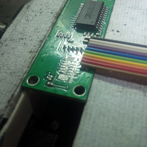
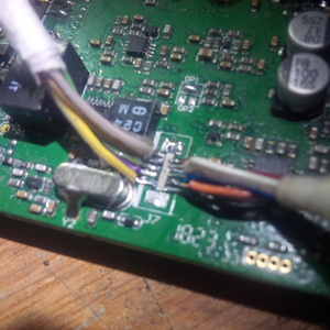
The flexi cable connecting the CRT ONE PCB to the LCD PCB is very very brittle and should be removed first when performing any work on the inside of the CRT ONE because it can break easily and is impossible to replace or repair due to its very small size and very fine traces. Nevertheless, in case the flexi cable is busted, one option is to replace the entire cable and connector with simple wires: luckily the CRT ONE is rather spacey on the inside such that very small cables are easy to fit.
The following is a diagram indicating how to match up the wires with just the extreme wires connected - fortunately, the solder pads are keyed such that 5 cables on one PCB will match 5 wires on the other PCB in order:
 +------------+
 |            |
 | | | | |    |
| | | | |     |
        |     |
 +------|-----+
 |      +---+
 |          |
 | | | | |  |
| | | | |   |
        |   |
        +---+
Once completed, the wires can be tucked neatly underneath the front bezel plastic using heat shrink tubes or clamped together using zip ties.
For the contact, copyright, license, warranty and privacy terms for the usage of this website please see the contact, license, privacy, copyright.
