Table of Contents
Parallelogram Rule for Addition of Forces
![LaTeX
\begin{tikzpicture}
% grid
\draw[help lines] (-4,-4) grid (4,4);
% mass
\node [square,minimum size=20mm] at (0, 0) [draw] (O) [lightgray,fill,text=black] node [anchor=south east] {$O$};
% coordinates
\coordinate (O) at (0,0);
\drawpoint{O}{.5mm}{black}
\coordinate (F1) at (3,2.5);
\coordinate (F2) at (-0.5,-3);
\coordinate (YM1) at (0, -4);
\coordinate (YM2) at (2.5,-4);
\coordinate (YM3) at (3,-4);
% forces
\draw [>=latex,draw=blue,fill=blue,->] (0,0) -- (F1) node[anchor=south east] {$A$};
\draw [>=latex,draw=blue,fill=blue,->] (0,0) -- (F2) node[anchor=south east] {$B$};
% guides
\draw [dotted,black] (O) -- (0,-4);
\draw [dotted,black] (F1) -- (3,-4);
\draw [dotted,black] (F2) -- (4,-3);
% angles
\markangle{O}{F2}{YM1}{7mm}{9mm}{$\alpha$}{red}{west}
\markangle{F1}{YM2}{YM3}{7mm}{9mm}{$\alpha$}{red}{west}
% paralleles
\draw [densely dashed,black,name path=f1 parallel] (F1) -- (2.5,-4);
\draw [densely dashed,black,name path=f2 parallel] (F2) -- (4,0);
\draw [densely dashed,black,name path=vector line] (F1) -- (F2);
% intersection resultant
\path [name intersections={of = f1 parallel and f2 parallel}];
\coordinate (R) at (intersection-1);
\drawpoint{R}{.5mm}{black}
% resultant
\draw [>=latex,draw=green,fill=blue,->,name path=resultant line] (0,0) -- (R) node[anchor=south east] {$F$};
% intersection vectors
\path [name intersections={of = vector line and resultant line}];
\coordinate[label={[black]above:$M$}] (M) at (intersection-1);
\drawpoint{M}{.5mm}{black}
\end{tikzpicture}](/lib/exe/fetch.php?media=wiki:latex:/imgc50d1e86f9eec6677240a2880b92d08b.png)
Suppose we have a coordinate system with two points  and
and  and the origin
  , then the length of the vector
  defines the magnitude of the force
  given by the scalar value of
  :
:

symmetrically the length of the vector  defines the magnitude of the force
  given by the scalar value of
  :
:

The sum of the two forces  and
and  applied in the point-mass
  can be computed from the sum of the segments that define them.
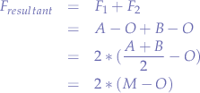
Let  and
and  , then the sum of the two vectors is:

where  is the midpoint of the segment
  . Thus the resulting force
  is:
is:

The scalar value of  is given by:

Note that in the illustration shows an ideal case where the  component is zero and forces are applied from the origin (point-mass force).
Analytical
In Euclidian space  the resultant force
  can be calculated as
  such that:

where  represents the basis vectors:

this can be generalised to n-dimensional Euclidian space by extending the components of the vectors.
The magnitude of the vector  is given by the scalar
  :
:

Vector Angle to Axis
![LaTeX
\begin{tikzpicture}
% grid
\draw[help lines] (-4,-4) grid (4,4);
% coordinates
\coordinate[label={[black]below left:$O$}] (O) at (0,0);
\drawpoint{O}{.5mm}{black}
\coordinate (F1) at (1.3,1.88);
\coordinate[label={[black]below:$P_{x}$}] (F1X) at (1.3,0);
\drawpoint{F1X}{.5mm}{black}
\coordinate (F1Y) at (0,1.88);
\drawpoint{F1Y}{.5mm}{black};
% forces
\draw [>=latex,draw=blue,fill=blue,->] (0,0) -- (F1) node[anchor=south east] {$A$};
% guides
\draw [dashed,black] (O) -- (0,-3);
\draw [solid,black,->] (O) -- (0,3) node[anchor=south] {$y$};
\draw [solid,black,->] (O) -- (3,0) node[anchor=south] {$x$};
\draw [dashed,black] (O) -- (-3,0);
% projections
\draw [dashed,black] (F1) -- (1.3,0);
\draw [dashed,black] (F1) -- (0,1.88);
% angles
\markangle{O}{F1}{F1X}{7mm}{9mm}{$\alpha$}{red}{west}
% braces
\drawbrace{O}{F1X}{2mm}{black}{$a_{x}$}{0}{-4mm}{mirror}
\end{tikzpicture}](/lib/exe/fetch.php?media=wiki:latex:/img3ea83d4edea9352c17ae450d7518d31d.png)
For a vector in 2D defined as:

with the basis vectors:

in the triangle  we can write that:

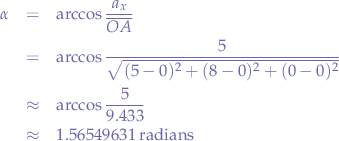
due to the right angle formed by  . Thus, we can deduce that the angle
  (in radians) is:

Note that the length of the segment  is given by the magnitude of the vector
  and that
  represents the component of the vector
  on the
  axis.
axis.
Example
Let us take a real-world scenario. We want to calculate the direction of the wind in terms of bearing (North, South, East, West) and we know that the measured wind vector is:

For aesthetics, let us presume that the axis  represents
 North and that the axis  represents
 East (with West and South in the respective inverse sense of the axis). Now we take the vector  and want to point in the direction of the wind. In order to do that, we perform the calculations above an obtain the angle
  :
:

and converting to degrees, we obtain:

This means that we have to rotate an arrow, or a pointer, starting from the  axis, approximately
  towards the axis that we have decided represents
 North. The result makes sense if you think about it, because the vector  is in the first trigonometric quadrant (more than zero and less than
 90 degrees). So, interpreting the result, the wind direction is approximately towards the North-North East.
Unit Vector Between Two Points
Given two points in cartesian space  and
and  , we want to find the unit vector between those points. First, we establish from which point to which point the direction should be.
For example's sake, let us assume that we want to find the vector that points from  to
to  . In that case, the vector is:

In order to find the unit vector, we dive the vector  with its magnitude. In other words:

In order to compute  we can use the cartesian notation of vectors using matrices, such that:

and the magnitude of the vector  is given by the scalar
  :
:

Example
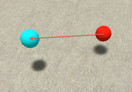
Using Second Life, Suppose we have two arbitrarily disposed masses in space, the red ball and the cyan ball:
and that we want to apply an impulse to the red ball, such that it travels towards the cyan ball.
In order to propel the red ball towards the the cyan ball, we apply the formulas above as a script inside the red ball. We perform the following calculations in succession:
- First, determine
 .
. - Compute the unit vector
 .
. - Apply a velocity as
 .
.
// velocity in m/s
float velocity = 1;

default {
    state_entry() {
        // scan for an object named cyan
        llSensor("cyan", "", ACTIVE|PASSIVE, 96, TWO_PI);
    }

    // when the cyan ball is found
    sensor(integer num) {
        // calculate the vector between the cyan ball and the red ball
        vector f = llDetectedPos(0) - llGetPos();
        // calculate the unit vector
        vector u = (f)*1/llVecMag(f);
        // apply an impulse to the red ball
        llSetVelocity(velocity * u, FALSE);
    }
}
The unit vector u gives us the direction and the scalar velocity gives us the speed. The reason for having an unit vector is that we leave it up to the scalar multiplier u to give us the velocity.
Universal Attraction of Masses
The law for universal attraction of masses is given by the formula:

where:
 is a gravitational constant,
  ,
, is the mass of one object,
 is the mass of the other object, and
 is the distance between the two masses.
Simulating in Second Life
As a small application of our cyan and red balls, let us rename both balls to mass and size them so that their sizes are equal. Under these constraints, we can use the following script, placed in both balls to illustrate the universal attraction of masses:
default {
    state_entry() {
        // scan for an object named mass
        llSensorRepeat("mass", "", ACTIVE|PASSIVE, 96, TWO_PI, 1.175494351E-38);
    }

    // when the cyan ball is found
    sensor(integer num) {
        // calculate the vector between the cyan ball and the red ball
        vector f = llDetectedPos(0) - llGetPos();
        // calculate the unit vector
        vector u = (f)*1/llVecMag(f);
        // get the distance between the cyan ball and the red ball
        float d = llVecDist(llDetectedPos(0), llGetPos());
        // the force is equal to the directional vector times the
        // mass squared and divided by the distance between the masses
        llSetForce(u * llPow(llGetMass(), 2)/d, FALSE);
    }
}
Since we now know how to use the directional vector u from the previous section, we can now set the force as the unit vector u times the force. Since we have said that we will consider the masses to be equal, we can just square the masses instead of doing  and then divide with the distance between them.
The masses do not necessarily have to be the same, however, in Second Life, it is impossible to detect the mass of an object. A different restriction is the force is applied every  which is roughly the resolution that events in Second Life are capable of.
Orbits
One consequence of the universal law of attraction is the creation of orbits.
Given two masses, the following observations can be made initially:
- the two masses attract each other due to the universal law of attraction.
- due to centripetal forces, one of the masses may miss the other, thus going on a curvature in space.
- if we take the other mass as a reference point, due to the constant application of the universal law of attraction of masses, a continuous force will pull the mass on the curvature towards the mass of reference.
In the real world, given the lack of constant acceleration, the orbit decays. This can be explained by looking at the forces exerted upon the orbiting object.
![LaTeX
\begin{tikzpicture}
% grid
\draw[help lines] (-3,-3) grid (3,3);
% origin
\draw[red, line width=.1mm] (-0.1,-0.1) -- (0.1,0.1)
(0.1,-0.1) -- (-0.1,0.1);
\coordinate[label={[red]above left:$O$}] (O) at (0,0);
\coordinate[label={[red]above right:$A$}] (A) at ({0.05+cos(30)},{0.05+2*cos(30)});
\coordinate (C) at (2,1);
\coordinate (D) at ({cos(30)-0.5},{2*cos(30)-1});
\coordinate (R) at (1.4, 0.1);
\drawpoint{A}{.5mm}{red};
% alpha
\markangle{A}{O}{R}{3mm}{3mm}{$\alpha$}{cyan}{north}
% circle
\draw [black, dotted] (0,0) circle [radius=2];
\draw [black, dotted] (A) -- (O);
\draw [blue,->] (A) -- (C) node [label={[blue]above right:$\overrightarrow{F_{c}}$}];
\draw [blue,->] (A) -- (D) node [label={[blue]above left:$\overrightarrow{F_{a}}$}];
\draw [blue,->] (A) -- (R) node [label={[blue]right:$\overrightarrow{R}$}];
\draw [black, dotted] (R) -- (C);
\draw [black, dotted] (R) -- (D);
%\drawbrace{O}{A}{2mm}{blue}{$r$}{-4mm}{0}{};
\end{tikzpicture}](/lib/exe/fetch.php?media=wiki:latex:/img233df45e598c7e5c4453a501892fc1db.png)
Suppose that the object is in  and that the initial force
  acts upon the object, that the force due to the universal attraction of masses is
  and that the resultant is
  . In the triangle formed by
  we can write:

and thus:

and if the initial force  is gradually diminished we observe that the angle
  becomes smaller such that eventually:

the angle will be  , thus pulling the object towards the object
  . Object
  's orbit will decay and eventually collide with object
Centripetal Force
![LaTeX
\begin{tikzpicture}
% grid
\draw[help lines] (-3,-3) grid (3,3);
% origin
\draw[red, line width=.1mm] (-0.1,-0.1) -- (0.1,0.1)
(0.1,-0.1) -- (-0.1,0.1);
\coordinate[label={[red]above left:$O$}] (O) at (0,0);
\coordinate[label={[red]above right:$A$}] (A) at ({0.05+cos(30)},{0.05+2*cos(30)});
\coordinate (C) at (2,1);
\coordinate (D) at ({cos(30)-0.5},{2*cos(30)-1});
\coordinate (R) at (1.4, 0.1);
\drawpoint{A}{.5mm}{red};
% alpha
%\markangle{A}{O}{R}{3mm}{3mm}{$\alpha$}{cyan}{north}
% circle
\draw [black, dotted] (0,0) circle [radius=2];
\draw [black, dotted] (A) -- (O);
\draw [blue,->] (A) -- (C) node [label={[blue]above right:$\overrightarrow{v}$}];
\draw [blue,->] (A) -- (D) node [label={[blue]above left:$\overrightarrow{F_{c}}$}];
%\draw [blue,->] (A) -- (R) node [label={[blue]right:$\overrightarrow{R}$}];
%\draw [black, dotted] (R) -- (C);
%\draw [black, dotted] (R) -- (D);
%\drawbrace{O}{A}{2mm}{blue}{$r$}{-4mm}{0}{};
\end{tikzpicture}](/lib/exe/fetch.php?media=wiki:latex:/imgf0922f25535aeebc4669a2ecb9e59f16.png)
The magnitude of the centripetal force of an object of mass  moving at a tangential speed
  along a path with radius of
  is:
is:

in terms of angular velocity  , the equation can be written as:

where, in two dimensions:

and  is the change of angle in time.
Simulating in Second Life
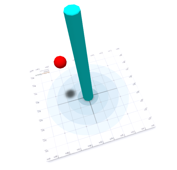
Given a central pole, and a ball that must rotate around the pole at a given velocity (here  ), the following script will:
- scan for the pole object (in
 ) intervals.
 - calculate the unit vector between the ball and the pole.
- calculate and apply the centripetal force.
- calculate the tangential unit vector (
 rotation around the unit vector between the ball and the pole).
 - calculate and apply the tangential velocity.
float velocity = 0.1;

default {
    state_entry() {
        // scan for an object named mass
        llSensorRepeat("pole", "", ACTIVE|PASSIVE, 96, TWO_PI, 1.175494351E-38);
    }

    // when the object is found
    sensor(integer num) {
        // get the position of the object
        vector oPos = llDetectedPos(0);
        // get our position
        vector mPos = llGetPos();
        // calculate the vector between the object and us
        vector f = <oPos.x, oPos.y, 0> - <mPos.x, mPos.y, 0>;
        // calculate the unit vector towards the object
        vector u = (f)*1/llVecMag(f);
        // calcualte the unit vector rotated by 90 (tangential)
        vector r = u * llEuler2Rot(<0, 0, 90> * DEG_TO_RAD);
        // get the distance between the object and us in the plane xOy
        float d = llVecDist(<oPos.x, oPos.y, 0>, <mPos.x, mPos.y, 0>);
        // compute the vector for the centripetal force
        vector fc = u * (llGetMass() * llPow(velocity,2)/d);
        // compute the vector for the velocity
        vector v = r * velocity;
        // set the centripetal force
        llSetForce(fc, FALSE);
        // set the tangential velocity
        llSetVelocity(v, FALSE);

    }
}
The velocity is favourably selected as being small  in order to counter the effect of the application of the centripetal force
 fc every  . In reality, the centripetal force
  is applied all the time and not in
  intervals, which, in the simulation's case, makes the ball gradually spiral away from the pole.
For the contact, copyright, license, warranty and privacy terms for the usage of this website please see the contact, license, privacy, copyright.


