This is an old revision of the document!
Table of Contents
List of USB Ports in Aspire One 110/150
- CN18 motheboard left side external (USB port, next to Ethernet)
- Daughter board right side external
- Daughter board right side external
- CN11 motherboard internal
Right next to the Intel Southbridge Controller we have the unused CN11 connector for SSD (page22). The schematic is as-seen from the underside of the motherboard:
                             SSD_LED#
                                 <----------------+
                                                  |
                   +5V                            |
                    +                CN11         |
                    |             1+---------+    |
                    +--------------+ +5V  NC +-2  |
        USBP3- <>---|--------------+ USB- NC +-4  |
        USBP3+ <>---|--------------+ USB+ NC +-6  |
               +----+ C149    +----+ GND  NC +----+ 8    <-- sandisk
               |    | 10u/10V |   7|      NC +----+ 10   <-- intel
     C154     -+-  -+-       -+-   +---------+
     0.1u/10V -+-  -+-       -+-
               |    |         |
              -+-  -+-        |
               -    -        -+-
                              -
The USB leads on the CN11 are on the side closest to the Southbridge and numbered Q1 to Q4. A sketch from the top part of the motherboard is the following:
   +---------------+
   |               |
   |               |
   |  Southbridge  |
   |               |
   |               |
   +---------------+ 7
      GND (black) <--+ +
       D+ (green) <--+ +
       D- (white) <--+ +
      5V+ (red)   <--+ +
                     1 ^
                       |
                       |
                       | NCs (ignore)
The last two leads Q3 and Q4 are placed slightly under the plastic glue that holds the Southbridge onto the motherboard (pins 7 to 1 on the previous sketch). It can be pushed aside slightly or cut and melted using a good cutter. The reason that you cannot connect to the bottom side of the motherboard to CN11 is that the HDD sits directly on top of it.
tnkgrl has an USB mod, but she pulls the leads from the SD connector directly from RN42 (by grafting wires on top of the SD connector pins). CN11 on the other hand is placed next to the trapdoor, on the bottom of the Aspire One, where you could slip a small USB hub.
- Camera internal (CN1 LCD connector pin 10 = D- and pin 11 = D+)
- 3G slot (Pin 36 = D- and pin 38 = D+)
- WLAN (WiFi) slot (Pin 36 = D- and pin 38 = D+)
- RN42 motherboard internal, near daughter board connector
Car Audio ISO Connector Pinout
ISO 10487 is a standard connector that is used in the radio unit (head unit). There are contacts for the power supply off / on (controlled by the ignition key), the speakers and automatic antenna.
SCV(speed-Dependent volume control). A speed sensor is hooked-up to this pin in order to boost up the volume. If the speedometer stops working when the radio is connected, this pin is grounded.Mute from Cell-Phone. Used to silence the audio, earthed by a connected mobile phone.- reversing light switch or GALA satellite signal (ping 1).
12V+when car is in gear to move backwards. - Memory Power (12V direct from Battery). Connects the radio directly to the battery.
- Power for Electric Antenna. Output from the radio
+12V(max150-300mA) power supply for electronic antennas. - Dial-light illumination (car side light circuit).
+12Vinput on the car when the lights are on. For some radios it illuminates the radio display, others can dim the lights. If the dashboard has light control, this pin should be connected in order to regulate the brightness. The wire from the cigarette lighter can be used for the same purposes. +12VMain power (switched by the ignition).12Vwith the ignition key is in theACCorONposition.- Ground (chassis).
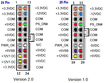
ATX Power Supply
Calculating Hard-Drive Space
To calculate the hard-drive space:

where  is the number of bytes.
Floppy Power Connector
      ||
    +---------------+
    | *   *   *   * |
    +---------------+
      ^   ^   ^   ^
      |   |   |   |
      |   |   |   |
     red  | black |
     +5V  |  GND  |
          |       |
          |       |
        black   yellow
         GND     +12V
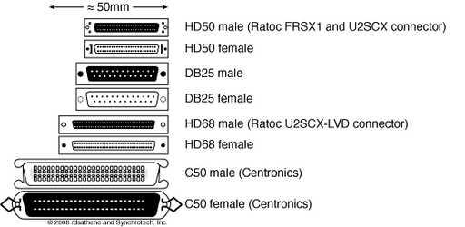
SCSI Connectors Aspect
Hard-Reset Dell Axim X5x
With the X50 turned on, press and hold the power button at the top of the unit. While holding the down power button, use the stylus tip to press the "Reset" button on the back. Allow the screen to fade to off. Release both buttons. The unit will power back on and display a menu to confirm the hard reset request. The Axim will be hard reset, just as it was when it left the factory.
Recovering OnTrack Disk Manager DM5 Drive
During the era (cca. 1993/4 the 2GB limit was prevalent in DOS before Windows95 OSR2 hard-drives that supported over 2GB limits, a 63-sector program called OnTrack sat as a DOS TSR and translated hard-drive calls by 63-sectors.
In Linux, using fdisk, assuming that the drive is /dev/sdb we can list the partition table and get something like:
Device      Boot Start     End Sectors Size Id Type
/dev/sdb1   *        9 5032943 5032935 2.4G 54 OnTrackDM6
To mount that partition directly, we can issue:
mount -o ro,loop,offset=64512 -t vfat /dev/sdb /mnt
where:
- 126 sectors are skipped (63 for DM6 and 63 for the original partition table.
Another approach is to use lopsetup:
umount /mnt
losetup /dev/loop0 /dev/sdb -o 32256
fdisk -l /dev/loop0
which should list all partitions. For instance:
      Device Boot      Start         End      Blocks   Id  System
/dev/loop0p1   *          63     4128704     2064321    6  FAT16
/dev/loop0p2         4192965    16434494     6120765    5  Extended
/dev/loop0p5         4193028     8385929     2096451    6  FAT16
So, to mount /dev/loop0p5 we would calculate  and then mount the partition:
losetup -d /dev/loop0
losetup -o 2146862592 /dev/loop0 /dev/sdb
mount -t vfat /dev/loop0 /mnt
VGA Port Dimensions
Removing Superglue from PCBs
 So, you're reading this. . .
In case you ever got the crazy idea of using superglue to fasten a component onto a PCB and now have a change of heart, the following procedure seems to work flawlessly and removes the superglue:
- use a screwdriver to very carefully pry the component off the board,
- smear a lot of resin based flux onto the board with the superglue residue,
- smear resin based flux onto some desoldering wick,
- heat up a solder gun to
 ,
, - place the wick onto the board and move it around whilst applying heat till the superglue residue liquefies - make sure to move around to not burn the PCB,
- quickly lift the solder gun and use a benzine soaked rag to wipe off the superglue liquid residue
Rinse and repeat as many times as necessary.
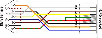
RJ-45 to DB-9 Cable
| RJ-45 (Signal reference from Chassis) | DB-9 (Signal reference from PC) | ||
|---|---|---|---|
| RTS | 1 | 8 | CTS |
| TX_Debug | 2 | 6 | DSR |
| TXD | 3 | 2 | RXD |
| GND | 4 | 1 | GND |
| DCD | 5 | 5 | DCD |
| RXD | 6 | 3 | TXD |
| RX_Debug | 7 | 4 | DTR |
| CTS | 8 | 7 | RTS |
| 9 | RI |
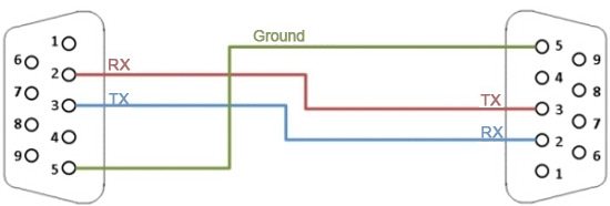
Simple Null Modem Cable
A male-to-male serial simple null modem cable.
Female-to-female serial simple null modem cables have the pins reversed to match.
Fixing Stuck CD Tray
Powering on Fujitsu DPS-800GB-3
Creating a Molex Power Distributor
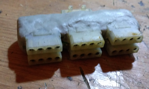
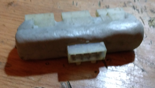
It appears that molex power distributors are tough to come by, perhaps due to the fact that all hardware is standardized and designed to reduce the number of cables necessary to wire a computer. When building a custom computer such as an Amiga with non-standard hardware, the cabling can become pretty complex such that the airflow within the chassis may end up greatly reduced and thereby increase the heat on various components.
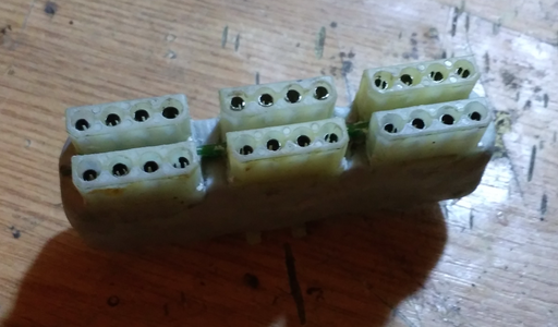
Using a simple blank PCB and 1-to-1 connections, as well as some magic putty a molex power distributor can be created that will provide power to various components from the same power outlet.
Magic putty is designed to be sanded down such that a nice finish can be given to the component after everything is checked to work correctly.
Note that the connections between the molex pins have to be perfect and continuity can be verified using a multimeter, preferably by testing with the built-in continuity tester as well as measuring resistance between the pins up to a few megohms.
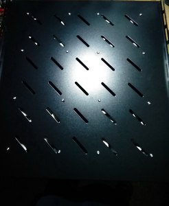
Creating an Affordable Tray Rack Fan
Tray rack fans are meant to be inserted between the various layers of servers in a rack cabinet. Unfortunately, tray rack fans seem to be rather expensive contrasted with how they are designed to operate: a rack fan consists more or less of 4 standard  PC fans, perhaps a switch, a potentiometer or a thermal sensor to regulate the speed. All of this comes at more or less USD100 and the price most likely gets inflated due to the equipment being considered "industrial" and meant for enterprises.
Requirements
- 19" Tray - USD15,
- 140mm PC fan with 2 or 3 pin headers - USD 6 / piece, 24 USD,
 to
to  step down converter,
- soldering, drilling equipment, etc.
Optional:
- [Optional] PCB
- [Optional] IC pin headers
Overall: about USD50.
Design
4 holes are drilled into the tray and the fans are mounted using nuts and screws onto the tray. The fan connectors are then connected to IC headers on a PCB that is fastened to the tray. A hole is drilled into the side of the tray and leads are drawn to the step down voltage converter in order to feed the fans. The PCB design just needs to pull  and
and  from the fan headers whilst ignoring the last pin which is the tachometer output signal. If a more complex design is required then perhaps the tachometer output signal could be read by an ESP microcontroller in combination with a thermal sensor.
However, most of the suggested complexity is not required and even the PCB can be left out at the cost of severing the connections between the fan headers and then connecting the leads directly to  whilst making sure that the fans are coupled in parallel.
Results
Building a Better NVME Heatsink
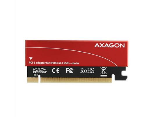
NVME tends to dissipate a lot of heat such that many heatsinks are too small to cool down the NVME module. One such case is an Intel NVME wrapped inside an "Axagon" heatsink.
The aluminum heatsik heats up way too much for the Intel NVME. One solution is to extend the heatsink using some RAM coolers such as the Arctic RAM module coolers. For a good thermal contact, the paint is brushed off the Axagon heatsink and off the Arctic RAM cooler. The two bare aluminium parts are then connected using a two-part Arctic thermal compound paste.
It does not matter which RAM module is used as long as it is good at dissipating heat - the Arctic RAM cooler was chosen due to the protruding lamelles that would help in dissipating the heat provided good airflow throughout the chassis.
Inventing a Backlit Desk Vice
Desk vises are frequently used for PCB repairs and sometimes it would be nice to be able to see through the PCB or ensure that the various circuit traces are in order. So why not add a backlight such that a PCB can be illuminated from the back and reveal any defects.
The design is rather simple and consists of an LCD strip and a step-up converter from  to
to  in order to allow the light to be powered via an USB connector. The design can be improved, perhaps by adding an UV light instead of the LCD strip in order to be able to see damages to the board due to capacitor leaks.
For the contact, copyright, license, warranty and privacy terms for the usage of this website please see the contact, license, privacy, copyright.
