Table of Contents
Amiga 1200 Motherboard Fixes
These are various fixes for different versions of the Amiga 1200 (Escom and Commodore) that will make the Amiga work better with an accelerator card from brands like Apollo and ACA. Note that Blizzard cards, albeit very expensive, are known to work without requiring these fixes.
- A1200 Rev 1D.4 with -01 Budgie:
- Remove E123C and E125C.
- A1200 Rev 1D.4 with -02 Budgie:
- Remove E123C and E125C.
- Remove XR358 "470 ohm pull-up resistor".
- Add 470 ohm pull-up resistor at DRA0, pin #43 of U2.
- A1200 Rev 2B with -01 Budgie:
- Remove E123C and E125C.
- A1200 Rev 2B with -02 Budgie:
- Remove E123C and E125C.
- Add 470 ohm pull-up resistor at DRA0, pin #43 of U2.
You can find the board revision written on the motherboard next to the expansion card slot (on the CPU side).
Power Supply Unit Pinouts
This pinout is consistent with the Amiga A500, A600 and A1200.
Commodore was never consistent with the wiring of the PSU power-plug however the following image depicts what each pin should be on an original Amiga PSU:
           +-----+     +-----+
           |      \___/      |
  +12V ------>*           * <----- GND (0V)
           |        *        |
           |        ^        |
           |     *  |  *     |
           |     ^  |  ^     |
           +-----|--|--|-----+
                 |  |  |
                 |  |  |
                 |  |
             Shield | +5V
                    |
                  -12V
As a correspondence between the Amiga PSU cable pinout and an ATX power-supply, we have the following:
| Amiga Colour | ATX Colour | Supply |
|---|---|---|
| Red | Red | +5V |
| Black | Black | 0V/GND |
| Brown | Yellow | +12V |
| White | Blue | -12V |
The shield pin can remain disconnected.
Reset Button for Amiga 1200
You can add a reset button to the Amiga by locating the slot TP1 on the upper-side of the motherboard and then connect the first and second pin to a "push-to-make" push-button switch.
             +-------+
              PCMCIA |
               Slot  |
             +-------+
                       +----+
                       |    |
                       +----+
                  TP1          +-+
                 +----------+  | |
    \ o------------* * ...  |  +-+
     \           +---|------+
      o--------------+
  Reset          +----------+
    Switch       | TP2 ...  |
                 +----------+
When the switch is pressed, the Amiga 1200 resets.
Installing Kickstart 3.1 ROMs in Amiga 1200
Dislodging the old ROMs can be performed by sliding a flat and slim screwdriver, or the can-opener of a Swiss Army Knife underneath the chips on both sides and slowly pulling them out. The new Kickstart ROMs can then be replaced with the 3991774 ROM at the top and the 3991773 at the bottom:
        ++--------------------------+
         |                          |
         |         3991774          |
         |                          |
        ++--------------------------+

        ++--------------------------+
         |                          |
         |          491773          |
         |                          |
        ++--------------------------+
        ^
        |
        |
        |
  Empty pin slots
   On the left
There will be two pin slots left empty for both ROMs and they have to be on the left-hand side of the ROMs.
Solving Dual Compact-Flash Adaptor Issues
It seems that some adaptors have trouble with some CF cards and a good fix is to attempt to switch the CF cards from one port to the other.
Using Sega Megadrive / Genesis Pads on The Amiga
A problem with using a Sega Megadrive or Genesis pad on the amiga is that there is a minor pinout mismatch concerning the +5V lead which is placed on a different pin between the Amiga and the Megadrive. The solution is to open the Megadrive controller and switch the leads 5 and 7.
   Sega Megadrive                          Amiga Joystick
   Select=GND / Select=+5V
   1 Up ---------------------------------- 1 Forward
   2 Down -------------------------------- 2 Back
   3 GND / Left -------------------------- 3 Left
   4 GND / Right ------------------------- 4 Right
   5 +5V ----------------------+   +------ 5 n/c
   6 Button A  / Button B----------|------ 6 Button 1
   7 Select-----------------+  +---|------ 7 +5V
   8 Ground --------------+ +------+ +---- 8 GND
   9 Start / Button C---+ +----------+ +-- 9 Button 2
                        +--------------+


                       1         5
                     +-------------+
                      \ o o o o o /
                       \ o o o o /
                        +-------+
                         6     9
Changing Capacitors on The Amiga 1200
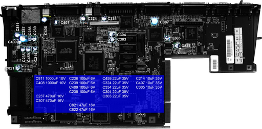
The capacitors in the original Amiga are bound to lose their capacitance over time and start to leak. Aside from the damage that the leaky capacitors may do to the motherboard, the usual consequences are distorted signals between various components of the Amiga - for example, a flicker of the image when large drawers are opened (to not be confused with the flicker of the image due to the mismatch of frequency between the Amiga video output).
The following instructional video is created by Amiga-Service and shows (German) how to replace all the capacitors on an Amiga 1200 motherboard.
It is the most complete guide to be found and the leaky SMD capacitors get replaced with ceramic capacitors that have a much larger time-span. There are other lengthy videos (not posted here) that show how to measure the signal output using an oscilloscope in order to determine whether you need to change the capacitors. Replacing the capacitors regardless, is still a safe bet due to the limited time-span of the SMD capa citors.
Capacitor Map
SMD Capacitors
| Designation | Capacity | Voltage | Part Number from Reichelt | Part Number from Kessler | Ceramic Capacitors from Reichelt |
|---|---|---|---|---|---|
| C822 | 47 uF | 16 V | SMD ELKO 47/16 | ES 47/16-SMD | X5R-G1210 47 |
| C306 | 10 uF | 35 V | SMD ELKO 10/35 | ES 10/35-SMD | X7R-G1210 10 |
| C303 | 22 uF | 25 V | SMD ELKO 22/25 | ES 22/25-SMD | X5R-G1210 22 |
| C304 | 22 uF | 25 v | SMD ELKO 22/25 | ES 22/25-SMD | X5R-G1210 22 |
| C??? | 22 uF | 25 V | SMD ELKO 22/25 | ES 22/25-SMD | X5R-G1210 22 |
| C324 | 22 uF | 25 V | SMD ELKO 22/25 | ES 22/25-SMD | X5R-G1210 22 |
| C??7 | 10 uF | 35 V | SMD ELKO 10/35 | ES 10/35-SMD | X7R-G1210 10 |
| C821 | 47 uF | 16 V | SMD ELKO 47/16 | ES 47/16-SMD | X5R-G1210 47 |
| C235 | 100 uF | 16 V | SMD ELKO 100/16 | ES 100/16-SMD | X5R-G1210 100 |
| C459 | 22 uF | 25 V | SMD ELKO 22/25 | ES 22/25-SMD | X5R-G1210 22 |
| C214 | 10 uF | 35 V | SMD ELKO 10/35 | ES 10/35-SMD | X7R-G1210 10 |
| C239 | 100 uF | 16 V | SMD ELKO 100/16 | ES 100/16-SMD | X5R-G1210 100 |
| C236 | 100 uF | 16 V | SMD ELKO 100/16 | ES 100/16-SMD | X5R-G1210 100 |
| C409 | 100 uF | 16 V | SMD ELKO 100/16 | ES 100/16-SMD | X5R-G1210 100 |
Cup Capacitors
| Designation | Capacity | Voltage | Part Number from Reichelt | Part Number from Kessler |
|---|---|---|---|---|
| C811 | 1000 uF | 10 V | RAD 1000/10 | EST 1000/10 |
| C237 | 470 uF | 16 V | RAD 470/16 | EST 470/16 |
| C408 | 1000uF | 10 v | RAD 1000/10 | EST 1000/10 |
| C307 | 470 uF | 16 V | RAD 470/16 | EST 470/16 |
FastATA
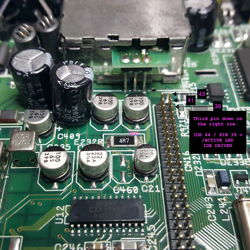
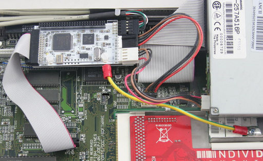
The ELBOX FastATA adapter whilst being a great piece of hardware - unfortunately the manual contains a very poor picture on where to connect the small wire that should connect to a pin on the IDE port.
The pin that the black wire connects to from the FastATA is the third pin on the right row from top to bottom: it corresponds to the IDE 44 pin number 39 which is the /ACTIVE LED DRIVER which is responsible to signal accesses to the FastATA.
Amiga 5.25" Compatible Floppies
With Commodore 1541 drive:
- 5.25" DS (Double Sided) DD (Double Density) 40 TPI (Tracks Per Inch) or 80 TPI (Tracks Per Inch).
- 5.25" DS DD 96 TPI
HD (High Density) do not work.
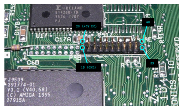
Amiga 1200 Clockport
There are two clockport ports on the Amiga 1200 motherboard:
P9BP9A
where the P9B should not have any header attached on more modern revisions since it is an interface to the DRAM.
P9A on the other hand is the clockport - there is no pin 1 but rather the counting starts on the bottom left with pin 19 that corresponds to the ground. The upper part continues with pin 20 which is  DC and the main means of powering any attached device.
All the pins, with the corresponding signals:
20  | 22  | 24  | 26  | 28  | 30  | 32  | 34  | 36  | 38  | 40  |
19  | 21  | 23  | 25  | 27  | 29  | 31  | 33  | 35  | 37  | 39  |
Clockport cable orientations are arbitrary relative to the red strip: in some cases the red strip appears to the right, towards  and
and  and sometimes it appears to the left, towards
  and
and  . There is no way to tell when attaching devices, except for using a continuity tester and checking that the ground and tension line correspond.
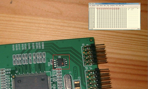
Re-programming NEC-based USB PCI Card for Amiga Mediator
NEC D720101GJ chipset cards can have their vendor ID modified such that Mediator boards made by Elbox will recognize the card as a valid USB expansion card.
Image from Amibay.
The main reason for performing this modification is that Elbox has the PCI Mediator locked to the Spider USB card that they are selling for a whooping USD75 whereas an identical flea-market NEC D720101GJ based card goes for about USD4.
Correct Wiring of RapidRoad USB
Troubleshooting Blizzard PPC Issues
In case the following symptoms are observed on a BlizzardPPC:
- booting with both mouse buttons held down yields no signal on the SCART and/OR RCA video line,
- pressing a button on the keyboard will output a very dark image of the Amiga boot screen,
- graphics corruption when loading Workbench, this includes:
- pointer being displayed as box,
- horizontal lines when forcing the output to NTSC for a PAL board
then the Blizzard PPC might have to be reflashed.
The procedure can be done without having to dismantle the board: download the latest Blizzard flash update from AmiNET and follow the instructions.
One addendum to the instructions is that whilst booting with 1, s or a held down, the Blizzard PPC turns off such that BlizzPPC0x0Update (where x is either 4 or 6) may claim that there no Blizzard PPC can be found. In that case, simply run BlizzPPC0x0Update from Workbench with the extra FORCE flag.
Blizzard PPC Overclocking
A Blizzard PPC card is shipped with the following possible configurations:
| m68k CPU | PowerPC 603e | SCSI Option |
|---|---|---|
68LC040-25 without FPU (A) | PowerPC603e 160Mhz (A) | with onboard SCSI (H) |
68040-25 with FPU (B) | PowerPC603e 200Mhz (C) | without onboard SCSI (I) |
68060-50 with FPU (H) | PowerPC603e 240Mhz (D) |
where any combination between columns is possible and the A, B, C, D, H and I markings are prefixes to the board serial number.
For instance, a serial number reading: HABXXXX will mean that the board is:
H- without SCSI,A- the PPC clocks at 160Mhz,B- has a040CPU clocked at 25Mhz
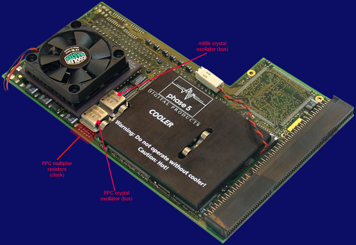
Using a standard image of a Blizzard PPC accelerator and annotating:
the following can be observed:
- the upper crystal oscillator is for the m68k CPU bus,
- the lower crystal oscillator is for the PPC CPU bus,
- slightly underneath the PPC crystal oscillator, an array of 5 resistors can be found that are used to set the PPC clock.
Noting that the total speed will be:

both CPUs on the Blizzard can be overclocked both by replacing the crystal oscillators and/or resoldering the resistors.
The resistors function as jumpers such that the resistors soldered closest to the PPC oscillators are 1 and the farthest soldered resistors are a logical 0. The left-most resistor is not used for overclocking and should not be tampered with. The possible configurations for the 4 remaining resistors, from left to right is shown in the following table:
| Resistors | Logical | Multiplier |
|---|---|---|
* * * * | 1000 | 3x |
* * *
     *
| 1110 | 3.5x |
* * * * | 1010 | 4x |
* * * * | 0111 | 4.5x |
* * * * | 1011 | 5x |
* * * * | 1001 | 5.5x |
* * * * | 1101 | 6x |
As an example, looking at the stock image, it seems that the value of crystal oscillator for the PPC is 50Mhz and the resistors are configured for a 3.5 multiplier giving a total of 175Mhz.
For overclocking the m68k CPU the only option is to replace the upper crystal oscillator with higher values.
Experiments show that if the BlizzardPPC board has an onboard SCSI, then overclocking the m68k CPU above 66Mhz will render the SCSI unusable - if a BVision card is added, it will also not function if the m68k CPU is overclocked beyond 66Mhz.
The best results for overclocking the m68k CPU seem to be achieved with Motorola 68060 CPUs that have higher revisions, ranging from 0 to 6 - where revision 6 carries the mask 71E41J, since higher revision CPUs tend to run very cool compared to the lower revisions.
It is highly indicated to add an additional fan to the m68k CPU for overclocking: a fitting heat sink and/or fan for the 68060 CPU should have the dimensions  since the CPU seems to be
  larger in both width and height.
Experiences
Blizzard PPC boards are designed and sold with the following options:
68040or68060at respectively
  ,
,- PowerPC 603e @
 ,
,  and
and  ,
,  ,
,  and
and  PowerPC bus
It stands to reason that there exists one single board design (not mentioning the DCE or Phase5 variations) that is then fitted with two CPUs and their matching crystal oscillators that would then yield all the options. Having that in mind, a good measure of how much to overclock is by taking the absolute maximum performance of the board 
68060,  PowerPC and a bus of
  since the board is designed to withstand the speeds such that all the overclock options will then hinge solely on the CPU dies. That being said, just overclocking to the maximum speed that the board was designed for in some ways is not overclocking at all and the actual overclock pertains more to overclocking the CPUs.
From the Internet, the following speeds have been achieved and there are Blizzard PPC boards sold with the following stats:

68060(overclocked from die),
die), PowerPC (fitted)
From our own experiences, the following can be achieved:

68060(overclocked from die),
die), or
or  PowerPC to
  - going from
  to
to  makes the PPC crash
and the Blizzard PPC seems stable.
It is a good idea to locate some  or
or  RAM sticks, albeit very rare, in order to be able to withstand the bus speed overclock.
Overclocking the Voodoo Graphics Card
All Voodoo cards can be overclocked just by setting the memory frequency. For instance, a Voodoo3 2000 at  can be made to run at
  (the speed of a Voodoo3 3000) and, in some cases, beyond and up to
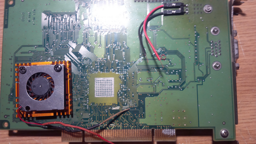
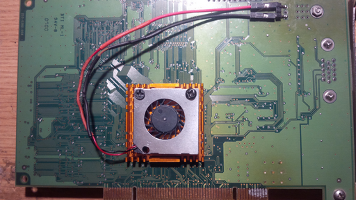
  . In order to overclock the Voodoo, extra cooling is recommended. Some Voodoo3 2000 models come with a large heatsink placed on top of the GPU such that only good ventilation is needed. Nevertheless, on the back of the card, the GPU has some aluminium traces exposed that are just ripe for attaching an extra heatsink and possibly a low-profile fan.
In order to be able to change the fan, an IDC strip is cut and soldered to the pins of the power transistor on the front side of the card. Using dupont wires, the connection is made to the fan and the heatsink is fixed on the back of the card with some heat transfer tape.
This way, both the front side of the GPU is cooled and the reverse is also cooled using an extra heatsink and fan.
For the software part, the Voodoo monitor file icon (conventionally placed at DEVS:Monitors/Voodoo) needs to have the following tooltypes enabled:
Overclock=Yes
MemoryClock=167
where  is the frequency in
  . As a simple rule to remember, with proper cooling, a Voodoo card can be easily overclocked to one model up (ie: Voodoo3 2000 to Voodoo3 3000). Anything above that is up for experimentation.
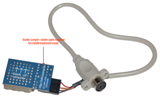
Closing the Solder Jumper on the Lyra 3 Adapter in order to Connect an A2000 Keyboard
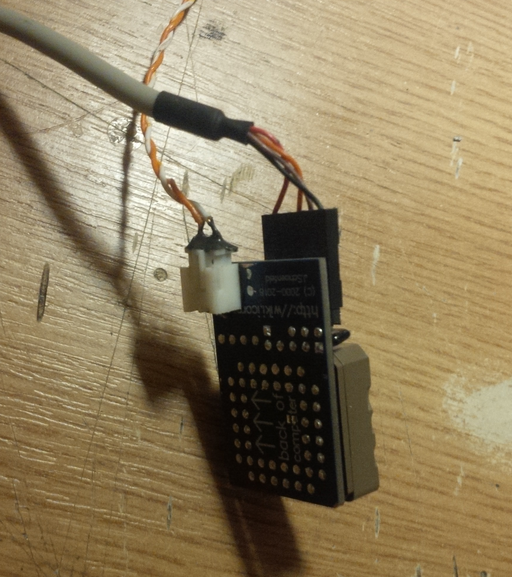
The Lyra 3 for the Amiga 1200 has one jumper that allows switching the Lyra 3 into an operating mode that allows an external A2000 keyboard to be connected and used with the Amiga 1200.
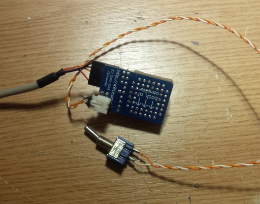
Adding a Switch to the Lyra 3 Adapter
A switch can be added to the Lyra 3 adapter in order to allow switching from PS/2 keyboards to Amiga keyboards with ease.
With the switch added to the Lyra 3, a hole can be drilled into the Amiga case and added externally.
Solving Issues with Elbox Black Case and Accelerator Boards
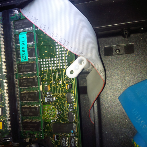
Yet another outstanding problem with the Elbox Black Case is that the accelerator card has no holder such that the accelerator card wobbles on the inside. At best, it remains propped against the case or leans back onto the power supply. This is a horrible design that is just looking to destroy any accelerator card. To solve the issue a hole can be drilled next to the accelerator and a strut added that can be moved in and out of place in order to allow the accelarator to be stable or to remove the accelerator card.
The white strut is a PCB distancer that has been sawed to adjust the distance between the accelerator and the case.
Proper Clockport Connection for Various Amiga Hardware
Connecting hardware the wrong way to the Amiga clockport can damage the motherboard and any attached cards. Unfortunately, there is a lot of confusion around the clockport connector: some Amigas have a full length clockport, some hardware creators mislabel pin 1, some cables are twisted instead of straight, etc. The following section will show some pictures on how to connect various Amiga hardware to the clockport.
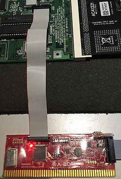
Prisma Megamix
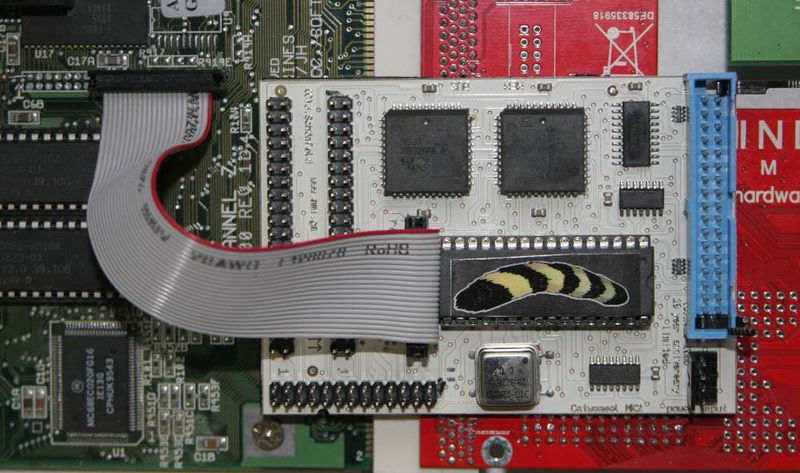
Catweasel
Strange Amiga Behaviour with PC ATX Power Supply
An ATX power supply can and probably should be used with a towerized Amiga in order to provide the extra wattage needed to drive more modern Amiga addons such as the Mediator to support PCI cards. However, modern ATX power supplies have a  lead, usually marked with a purple wire inside the power supply, that is rated at about
  and constantly supplies power to the PC motherboard.
Unfortunately, the Amiga relies on being completely powered down - the Amiga works on the assumption that eventually the computer will be turned off and this fact is used to expunge and clean stored parameters in RAM. A residual current from the  lead will prevent the Amiga from being fully powered off.
This results in the Amiga displaying a wide range of errors, mainly red screen (ROM error, probably due to the accelerator mapping the ROM into RAM and the RAM never being properly flushed), culminating with the accelerator not even booting.
To remedy the issue, simply sever the purple wire inside the ATX power supply and do not provide power via the purple wire to the Amiga. Ensure that the Amiga will fully power off with no residual (or as little as possible) flowing through the circuits.
For the contact, copyright, license, warranty and privacy terms for the usage of this website please see the contact, license, privacy, copyright.
