Table of Contents
About
The following project involves using an ESP controller board in order to read data from a Victron Energy device by following the VE.Direct protocol as described by the creators of Victron Energy devices. The code provided is generic enough to handle all Victron Energy devices due to being device-agnostic and not implementing any device-specific primitives. The code reads data published by Victron Energy devices from the serial port, accumulates a VE.Direct frame and proceeds to compute the checksum. If the checksum is valid, as per the protocol description, then the frame is published via MQTT. As usual with Wizardry and Steamworks templates, the Arduino code does not perform any heavy or unnecessary computations but rather restricts itself to processing the data and then sending that data over to a data centralization server such as Node-Red where further processing is left up the user.
Requirements
- A Victron Energy device. For this example, a Victron Inverter was chosen.
- An ESP device (ESP32, 8266, etc) and it does not matter much what type it is as long as it has WiFi capabilities and an accessible serial port. In fact, for this project, a WeMoS D1 mini clone was used regardless if it has only one single serial port.
- A step-down buck converter to bring down
 to
to  .
.
Diagram
The following sketch illustrates the connections between the Victron Energy device, the ESP and the step-down buck converter.
The main highlights are that the ESP will be powered via a step-down buck converter that feeds directly off the Victron Energy power lines instead of connecting the ESP directly to the Victron Energy serial port and using the serial port provided power. In doing so, the Victron Energy serial port is better protected and the ESP can draw as much power as it likes without overburdening the serial port power lines.
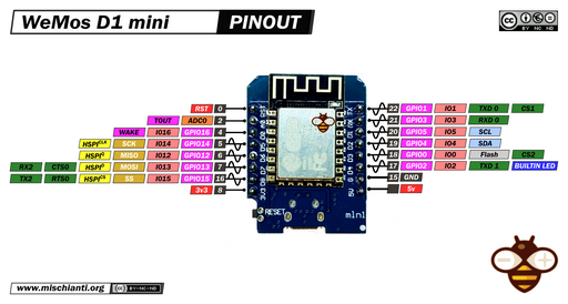
Any ESP that can do WiFi and has a serial port can be used and we used a WeMoS D1 mini clone by connecting the Victron Energy RX and TX lines to the RX and TX pins of the WeMoS.
Unfortunately, the RX and TX pins of the WeMoS are connected directly to the USB port serial input and output such that debugging will have to rely on sending data to MQTT instead of using functions such as Serial.print to debug the Arduino sketch.
Realization
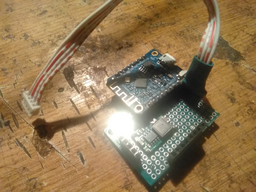
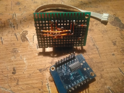
The realization is nothing too fascinating. The build is kept small by placing the step down buck converter underneath the WeMoS that, in turn, is raised on top with connectors in order to allow the WeMoS to be removed. One side of the board provides power for the WeMoS and the other connects just the middle pins to the serial port of the Victron Energy device. The other pins of the serial connector (the pins at the extremities) that provide  , respectively grounding are floating and completely ignored by the WeMoS.
The circuit is traced underneath the board using copper wires that are bent to shape in order to make the connections between the various components.
The VE.Direct Protocol
Fortunately, Victron Energy provides ample documentation that describes the communication protocol on their websites and for this case where a Victron Energy Phoenix Inverter is used as an example, the following documentation is useful:
In brief, once the serial connection is made to the Victron Energy device, the device will start sending textual data over the serial port. The data is emitted line-by-line, each line deemed to be a message where all messages taken together and bounded by a checksum marker constitute a frame. The aspect of the data observed in raw format is somewhere along the lines of the following frame in hexadecimal format:
00000000  0d 0a 50 49 44 09 30 78  32 30 33 0d 0a 56 09 32  |..PID.0x203..V.2|
00000010  36 32 30 31 0d 0a 49 09  30 0d 0a 50 09 30 0d 0a  |6201..I.0..P.0..|
00000020  43 45 09 30 0d 0a 53 4f  43 09 31 30 30 30 0d 0a  |CE.0..SOC.1000..|
00000030  54 54 47 09 2d 31 0d 0a  41 6c 61 72 6d 09 4f 46  |TTG.-1..Alarm.OF|
00000040  46 0d 0a 52 65 6c 61 79  09 4f 46 46 0d 0a 41 52  |F..Relay.OFF..AR|
00000050  09 30 0d 0a 42 4d 56 09  37 30 30 0d 0a 46 57 09  |.0..BMV.700..FW.|
00000060  30 33 30 37 0d 0a 43 68  65 63 6b 73 75 6d 09 d8  |0307..Checksum..|
which corresponds to the Victron Energy specification of the VE Direct protocol, as a collection of \r\n delimited tabular messages that constitute a frame, with the following grammar:
<Newline><Field-Label><Tab><Field-Value>
where:
- the newline is made up out of a Windows-style carriage return using the sequence of characters
\r\n, - the field label is a textual marker describing a key, followed by,
- a tab character and followed by,
- the value of the field label
For instance, looking at the raw data above, one of the messages is:
PID 0x203
and the next message is:
V 26201
and so on till the end of the frame that ends in:
Checksum ?
where ? is a placeholder for a character that is to be interpreted numerically rather than textually.
All the messages taken together, starting with the first \r\n marker and ending with the checksum followed by a padding value constitute a frame. In order to compute the checksum for the frame, the specification mentions that all the raw values taken numerically have to be added together whilst applying modulo 255. Iff., at the end of the calculation, the computed value modulo 255 is zero, then the frame passes the checksum check and is considered to be a valid frame.
For example, the provided Arduino code computes the checksum of the frame using the following function:
//https://www.victronenergy.com/live/vedirect_protocol:faq#q8how_do_i_calculate_the_text_checksum
// computes the checksum of a VEDirect frame
// return true iff. the checksum of the frame is valid.
bool isVEDirectChecksumValid(String frame) {
  int checksum = 0;
  for (int i = 0; i < frame.length(); ++i) {
    checksum = (checksum + frame[i]) & 255;
  }
  return checksum == 0;
}
The frame parameter of the isVEDirectChecksumValid is a large buffer that contains the entire raw frame, starting with the initial \r\n and ending with the checksum padding value.
Code
The code is designed to perform the following operations:
- initialize the serial port to
19200as per the Victron Direct protocol specification, - connect to a configured MQTT broker,
- use the Arduino
serialEventfunction in order to asynchronously process serial messages to be processed
Upon every raise of the serialEvent function, the following operations are performed:
- one character is read and added to a buffer
veFrameBuffer, - the code attempts to match the buffer against the regular expression
Checksum\t.in order to determine whether the end of a frame has been reached, - if the end of the frame has been reached, then the checksum is computed via the
isVEDirectChecksumValidin order to determine whether the frame is valid and if the frame is not valid, it is then discarded, - if the frame passes the checksum check, then the sketch will start progressively matching the frame using the regular expression defined in
VE_DIRECT_MESSAGE_REGEX, that is,\r\n([a-zA-Z0-9_]+)\t([^\r\n]+)in order to extract each message from the frame using regular expression groupings, - the groups are then appended to a JSON object, where the first regular expression group corresponds to a key and the second regular expression group is the value corresponding to the key, and the checksum group is discarded because it is useless outside of the context of the VE Direct frame,
- the JSON object is then published to the configured MQTT broker
The aspect of the published JSON data will have the following example shape for a Victron Energy power inverter:
{
   "PID":"0xA231",
   "FW":"0126",
   "MODE":"2",
   "CS":"9",
   "AC_OUT_V":"23007",
   "AC_OUT_I":"0",
   "AC_OUT_S":"0",
   "V":"12995",
   "AR":"0",
   "WARN":"0",
   "OR":"0x00000000"
}
where the respective keys such as PID, FW, MODE, etc, are defined an can be looked up in the specific device manual.
It would be possible to simplify the algorithm based on the fact that the VE Direct protocol published messages individually following the grammar:
<Newline><Field-Label><Tab><Field-Value>
such that only matching individual messages and publishing them would be possible but the algorithm implemented by the sketch is the only way to properly separate between frames, as well as checking for the consistency of the VE Direct frames by computing the checksum due to the Checksum field label being well-defined by the VE Direct protocol and constitutes an invariant for all devices made by Victron Energy.
That being said, the code is completely agnostic to the device type such that it is possible to use the same sketch with devices other than the Victron Energy Phoenix inverter.
At this time, the sketch does not implement changing settings for the Victron Energy device.
Sketch
/*************************************************************************/
/*    Copyright (C) 2023 Wizardry and Steamworks - License: GNU GPLv3    */
/*************************************************************************/
// Project URL:                                                          //
//  http://grimore.org/iot/reading_victron_energy_serial_data            //
//                                                                       //
// The following Arduino sketch implements a reader for all devices      //
// created by Victron Energy by following the VE.Direct Protocol         //
// description. The sketch captures VE.Direct frames, computes the       //
// checksum of each frame and if the frame is valid then a JSON payload  //
// is generated and published to an MQTT broker.                         //
//                                                                       //
// Connecting to a Victron Energy devices involves creating a cable that //
// is specific to the device to be interfaced with. However, the         //
// interface will always be an RS232 serial port interface such that the //
// serial ports on an ESP board can be used.                             //
//                                                                       //
// For example, a Victron Energy Power Inverter has a port on the upper  //
// side that consists in three pins, typically, from left-to right in    //
// order carrying the meaning: GND, RX, TX, 5V with the RX and TX having //
// to be inverted (crossed-over) in order to interface with the device.  //
//                                                                       //
// For simplicity's sake, the sketch just uses the default serial port   //
// which is the same one that is used typically to connect to the ESP    //
// board using an USB cable. By consequence, serial port functions such  //
// as Serial.println() should be avoided because they will end up        //
// sending data to the device instead of through the USB cable.          //
///////////////////////////////////////////////////////////////////////////

// Removing comment for debugging over the first serial port.
//#define DEBUG 1
// The AP to connect to via Wifi.
#define STA_SSID ""
// The AP Wifi password.
#define STA_PSK ""
// The MQTT broker to connect to.
#define MQTT_HOST ""
// The MQTT broker username.
#define MQTT_USERNAME ""
// The MQTT broker password.
#define MQTT_PASSWORD ""
// The MQTT broker port.
#define MQTT_PORT 1883
// The default MQTT client ID is "esp-CHIPID" where CHIPID is the ESP8266
// or ESP32 chip identifier.
#define MQTT_CLIENT_ID() String("esp-" + String(GET_CHIP_ID(), HEX))
// The authentication password to use for OTA updates.
#define OTA_PASSWORD ""
// The OTA port on which updates take place.
#define OTA_PORT 8266
// The default topic that the sketch subscribes to is "esp/CHIPID" where
// CHIPID is the ESP8266 or ESP32 chip identifier.
#define MQTT_TOPIC() String("esp/" + String(GET_CHIP_ID(), HEX))

// Platform specific defines.
#if defined(ARDUINO_ARCH_ESP8266)
#define GET_CHIP_ID() (ESP.getChipId())
#elif defined(ARDUINO_ARCH_ESP32)
#define GET_CHIP_ID() ((uint16_t)(ESP.getEfuseMac() >> 32))
#endif

// Miscellaneous defines.
//#define CHIP_ID_HEX (String(GET_CHIP_ID()).c_str())
#define HOSTNAME() String("esp-" + String(GET_CHIP_ID(), HEX))

// https://www.victronenergy.com/upload/documents/VE.Direct-Protocol-3.33.pdf
// matches a message from a VE Direct frame
#define VE_DIRECT_MESSAGE_REGEX "\r\n([a-zA-Z0-9_]+)\t([^\r\n]+)"

// Platform specific libraries.
#if defined(ARDUINO_ARCH_ESP8266)
#include <ESP8266WiFi.h>
#include <ESP8266mDNS.h>
#elif defined(ARDUINO_ARCH_ESP32)
#include <WiFi.h>
#include <ESPmDNS.h>
#endif
// General libraries.
#include <WiFiUdp.h>
#include <ArduinoOTA.h>
#include <PubSubClient.h>
#include <ArduinoJson.h>
#include <Regexp.h>
#if defined(ARDUINO_ARCH_ESP32)
#include <FS.h>
#include <SPIFFS.h>
#endif

WiFiClient espClient;
PubSubClient mqttClient(espClient);
StaticJsonDocument<512> veFrame;
String veFrameBuffer = "";

bool mqttConnect() {
#ifdef DEBUG
  Serial.println("Attempting to connect to MQTT broker: " + String(MQTT_HOST));
#endif
  mqttClient.setServer(MQTT_HOST, MQTT_PORT);

  StaticJsonDocument<256> msg;
  if (mqttClient.connect(MQTT_CLIENT_ID().c_str(), MQTT_USERNAME, MQTT_PASSWORD)) {
#ifdef DEBUG
    Serial.println("Established connection with MQTT broker using client ID: " + MQTT_CLIENT_ID());
#endif
    msg["action"] = "connected";
    char output[512];
    serializeJson(msg, output, 512);
    mqttClient.publish(MQTT_TOPIC().c_str(), output);
#ifdef DEBUG
    Serial.println("Attempting to subscribe to MQTT topic: " + MQTT_TOPIC());
#endif
    if (!mqttClient.subscribe(MQTT_TOPIC().c_str())) {
#ifdef DEBUG
      Serial.println("Failed to subscribe to MQTT topic: " + MQTT_TOPIC());
#endif
      return false;
    }
#ifdef DEBUG
    Serial.println("Subscribed to MQTT topic: " + MQTT_TOPIC());
#endif
    msg.clear();
    msg["action"] = "subscribed";
    serializeJson(msg, output, 512);
    mqttClient.publish(MQTT_TOPIC().c_str(), output);
    return true;
  }
#ifdef DEBUG
  Serial.println("Connection to MQTT broker failed with MQTT client state: " + String(mqttClient.state()));
#endif
  return false;
}

bool programLoop() {
  // Process OTA loop first since emergency OTA updates might be needed.
  ArduinoOTA.handle();

  // Process MQTT client loop.
  if (!mqttClient.connected()) {
    // If the connection to the MQTT broker has failed then sleep before carrying on.
    if (!mqttConnect()) {
      return false;
    }
  }
  return mqttClient.loop();
}

//https://www.victronenergy.com/live/vedirect_protocol:faq#q8how_do_i_calculate_the_text_checksum
// computes the checksum of a VEDirect frame
// return true iff. the checksum of the frame is valid.
bool isVEDirectChecksumValid(String frame) {
  int checksum = 0;
  for (int i = 0; i < frame.length(); ++i) {
    checksum = (checksum + frame[i]) & 255;
  }
  return checksum == 0;
}

void frameRegexMatchCallback(const char *match, const unsigned int length, const MatchState &ms) {
  // https://www.victronenergy.com/upload/documents/VE.Direct-Protocol-3.33.pdf:
  // k -> 9 bytes
  // v -> 33 bytes
  char k[9];
  ms.GetCapture(k, 0);
  char v[33];
  ms.GetCapture(v, 1);

  // The checksum is irrelevant since the frame has already deemed to be valid.
  if (String(k) == "Checksum") {
    return;
  }

  veFrame[k] = v;
}

void setup() {
  // https://www.victronenergy.com/upload/documents/VE.Direct-Protocol-3.33.pdf
  // baud: 19200
  // data bits: 8
  // parity: none
  // stop bits: 1
  // flow control: none
  Serial.begin(19200);

#ifdef DEBUG
  Serial.println("Booted, setting up Wifi in 10s...");
#endif
  delay(10000);

  WiFi.mode(WIFI_STA);
#if defined(ARDUINO_ARCH_ESP8266)
  WiFi.hostname(HOSTNAME().c_str());
#elif defined(ARDUINO_ARCH_ESP32)
  WiFi.setHostname(HOSTNAME().c_str());
#endif
  WiFi.begin(STA_SSID, STA_PSK);
  while (WiFi.waitForConnectResult() != WL_CONNECTED) {
#ifdef DEBUG
    Serial.println("Failed to connect to Wifi, rebooting in 5s...");
#endif
    delay(5000);
    ESP.restart();
  }

#ifdef DEBUG
  Serial.print("Connected to Wifi: ");
  Serial.println(WiFi.localIP());
  Serial.println("Setting up OTA in 10s...");
#endif
  delay(10000);

  // Port defaults to 8266
  ArduinoOTA.setPort(OTA_PORT);

  // Hostname defaults to esp-[ChipID]
  ArduinoOTA.setHostname(HOSTNAME().c_str());

  // Set the OTA password
  ArduinoOTA.setPassword(OTA_PASSWORD);

  ArduinoOTA.onStart([]() {
    switch (ArduinoOTA.getCommand()) {
      case U_FLASH:  // Sketch
#ifdef DEBUG
        Serial.println("OTA start updating sketch.");
#endif
        break;
#if defined(ARDUINO_ARCH_ESP8266)
      case U_FS:
#elif defined(ARDUINO_ARCH_ESP32)
      case U_SPIFFS:
#endif
#ifdef DEBUG
        Serial.println("OTA start updating filesystem.");
#endif
        SPIFFS.end();
        break;
      default:
#ifdef DEBUG
        Serial.println("Unknown OTA update type.");
#endif
        break;
    }
  });
  ArduinoOTA.onEnd([]() {
#ifdef DEBUG
    Serial.println("OTA update complete.");
#endif
    SPIFFS.begin();
#if defined(ARDUINO_ARCH_ESP8266)
    // For what it's worth, check the filesystem on ESP8266.
    SPIFFS.check();
#endif
    ESP.restart();
  });
  ArduinoOTA.onProgress([](unsigned int progress, unsigned int total) {
#ifdef DEBUG
    Serial.printf("OTA update progress: %u%%\r", (progress / (total / 100)));
#endif
  });
  ArduinoOTA.onError([](ota_error_t error) {
#ifdef DEBUG
    Serial.printf("OTA update error [%u]: ", error);
#endif
    switch (error) {
      case OTA_AUTH_ERROR:
#ifdef DEBUG
        Serial.println("OTA authentication failed");
#endif
        break;
      case OTA_BEGIN_ERROR:
#ifdef DEBUG
        Serial.println("OTA begin failed");
#endif
        break;
      case OTA_CONNECT_ERROR:
#ifdef DEBUG
        Serial.println("OTA connect failed");
#endif
        break;
      case OTA_RECEIVE_ERROR:
#ifdef DEBUG
        Serial.println("OTA receive failed");
#endif
        break;
      case OTA_END_ERROR:
#ifdef DEBUG
        Serial.println("OTA end failed");
#endif
        break;
      default:
#ifdef DEBUG
        Serial.println("Unknown OTA failure");
#endif
        break;
    }
    ESP.restart();
  });
  ArduinoOTA.begin();

  // Set up MQTT client.
  mqttClient.setServer(MQTT_HOST, MQTT_PORT);

  // Touchdown.
#ifdef DEBUG
  Serial.println("Setup complete.");
#endif
}

void loop() {
  // Check the Wifi connection status.
  int wifiStatus = WiFi.status();
  switch (wifiStatus) {
    case WL_CONNECTED:
      if (!programLoop()) {
        delay(1000);
        break;
      }
      delay(1);
      break;
    case WL_NO_SHIELD:
#ifdef DEBUG
      Serial.println("No Wifi shield present.");
#endif
      goto DEFAULT_CASE;
      break;
    case WL_NO_SSID_AVAIL:
#ifdef DEBUG
      Serial.println("Configured SSID not found.");
#endif
      goto DEFAULT_CASE;
      break;
    // Temporary statuses indicating transitional states.
    case WL_IDLE_STATUS:
    case WL_SCAN_COMPLETED:
      delay(1000);
      break;
    // Fatal Wifi statuses trigger a delayed ESP restart.
    case WL_CONNECT_FAILED:
    case WL_CONNECTION_LOST:
    case WL_DISCONNECTED:
    default:
#ifdef DEBUG
      Serial.println("Wifi connection failed with status: " + String(wifiStatus));
#endif
DEFAULT_CASE:
      delay(10000);
      ESP.restart();
      break;
  }
}

void serialEvent() {
  while (Serial.available()) {
    // get the new byte:
    char c = (char)Serial.read();
    veFrameBuffer += c;

    MatchState checksumMatchState;
    checksumMatchState.Target((char *)veFrameBuffer.c_str());
    char result = checksumMatchState.Match("Checksum\t.");
    // The checksum field that marks the end of the frame has been found.
    if (result == REGEXP_MATCHED) {
      // Compute the checksum and see whether the frame is valid.
      if (!isVEDirectChecksumValid(veFrameBuffer)) {
        // If the checksum fails to compute then the frame is invalid so discard it.
        veFrameBuffer = "";
        return;
      }

      // The frame is valid so match the individual messages.
      MatchState messageMatchState((char *)veFrameBuffer.c_str());
      messageMatchState.GlobalMatch(VE_DIRECT_MESSAGE_REGEX, frameRegexMatchCallback);

      // Publish the frame.
      char output[512];
      serializeJson(veFrame, output, 512);
      veFrame.clear();
      mqttClient.publish(MQTT_TOPIC().c_str(), output);

      // Reset the buffer.
      veFrameBuffer = "";
      return;
    }
  }
}
For the contact, copyright, license, warranty and privacy terms for the usage of this website please see the contact, license, privacy, copyright.


