Table of Contents
About
LED light strips are usually sold with a controller and a remote that allows the user to set the colors on the LEDs along with various programs that allow the LEDs to blink or to fade from one color to the other. In that case, the LED strip is limited to a certain amount of functions that are granted by the controller itself. It is much more interesting to build a LED light strip that is controlled programatically, preferably from a computer in order to be able to create more interesting functions or even set the colour of the strip in relation to some other IoT device.
Integrating a few Wizardry and Steamworks technologies, namely the Arduino LED light strip design with general purpose transitors, a hexadecimal to RGB converter in JavaScript as well as Node-Red, an IoT light strip can be built that will allow the colors to be set remotely from a micro-controller device.
Design
Given a  LED light strip, a stepdown converter is used to bring the power down from
  to
to  in order to power both an Arduino based on a WeMoS
 ESP8266 board and the LED strip itself. In spite of the fact that the WeMoS ESP8266board has only one analogical pin, the digital pins can be used to generate a PWM signal that will effectively approximate voltage between  and
and  . That being said, three general purpose transistors are used such as the
 2N3904 to drain the  fed to the light strip and through the
 R, G, and B leads to the ground.
The schematic is as follows:
                                            12V
      +-------------------------+------------->
      |                         |
   +--+--+                +-----+-----+
   | 12V |                | 12V -> 5V |
   +--+--+                +-----+-----+
      |                         |
      |                         |            R
      |          +---------+ 5V |   +--------->
      |      GND |         |----+   |
      +----------+         |        /
                 |    GPIO +------|+
                 |         |        \ e
                 |         |        v
                 |         |        |
                 |         |       GND
                 | Arduino |                 G
                 |         |        +--------->
                 |         |        |
                 |         |        /
                 |    GPIO +------|+
                 |         |        \ e
                 |         |        v
                 |         |        |
                 |         |       GND
                 |         |                 B
                 |         |        +--------->
                 |         |        |
                 |         |        /
                 |    GPIO +------|+
                 |         |        \ e
                 |         |        v
                 |         |        |
                 +---------+       GND
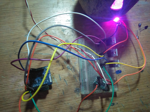
Using a prototyping board, the following construct is obtained:
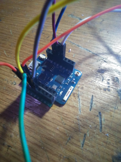
with a small modification to the WeMoS board to accommodate a ground bridge in order to allow for multiple Dupont cables to be connected to the ground:
Arduino Code
The code for the WeMos rather simple to write given previous Wizardry and Steamworks sketches such as the ESP pin toggler:
/*************************************************************************/
/*    Copyright (C) 2021 Wizardry and Steamworks - License: GNU GPLv3    */
/*************************************************************************/

// The AP to connect to via Wifi.
#define STA_SSID ""
// The AP Wifi password.
#define STA_PSK ""
// The MQTT broker to connect to.
#define MQTT_HOST ""
// The MQTT broker username.
#define MQTT_USERNAME ""
// The MQTT broker password.
#define MQTT_PASSWORD ""
// The MQTT broker port.
#define MQTT_PORT 1883
// The default MQTT client ID is "esp-CHIPID" where CHIPID is the ESP8266
// or ESP32 chip identifier.
#define MQTT_CLIENT_ID() String("esp-" + String(GET_CHIP_ID(), HEX))
// The authentication password to use for OTA updates.
#define OTA_PASSWORD ""
// The OTA port on which updates take place.
#define OTA_PORT 8266
// The default topic that the sketch subscribes to is "esp/CHIPID" where
// CHIPID is the ESP8266 or ESP32 chip identifier.
#define MQTT_TOPIC() String("esp/" + String(GET_CHIP_ID(), HEX))

// Platform specific defines.
#if defined(ARDUINO_ARCH_ESP8266)
#define GET_CHIP_ID() (ESP.getChipId())
#elif defined(ARDUINO_ARCH_ESP32)
#define GET_CHIP_ID() ((uint16_t)(ESP.getEfuseMac()>>32))
#endif

// Miscellaneous defines.
#define CHIP_ID_HEX (String(GET_CHIP_ID()).c_str())
#define HOSTNAME() String("esp-" + String(GET_CHIP_ID(), HEX))

// Platform specific libraries.
#if defined(ARDUINO_ARCH_ESP8266)
#include <ESP8266WiFi.h>
#include <ESP8266mDNS.h>
#elif defined(ARDUINO_ARCH_ESP32)
#include <WiFi.h>
#include <ESPmDNS.h>
#endif
// General libraries.
#include <WiFiUdp.h>
#include <ArduinoOTA.h>
#include <PubSubClient.h>
#include <ArduinoJson.h>
#if defined(ARDUINO_ARCH_ESP32)
#include <FS.h>
#include <SPIFFS.h>
#endif

// Define LED strip PWM pins.
#if defined(ARDUINO_ARCH_ESP8266)
#define R_PIN D5
#define G_PIN D6
#define B_PIN D7
#elif defined(ARDUINO_ARCH_ESP32)
#define R_PIN 33
#define G_PIN 34
#define B_PIN 35
#endif

const char *sta_ssid = STA_SSID;
const char *sta_psk = STA_PSK;
const char *mqtt_host = MQTT_HOST;
const char *mqtt_username = MQTT_USERNAME;
const char *mqtt_password = MQTT_PASSWORD;
const int mqtt_port = MQTT_PORT;
const char *ota_password = OTA_PASSWORD;
const int ota_port = OTA_PORT;

WiFiClient espClient;
PubSubClient mqttClient(espClient);

/*************************************************************************/
/*    Copyright (C) 2015 Wizardry and Steamworks - License: GNU GPLv3    */
/*************************************************************************/
int wasMapValueToRange(int v, int xMin, int xMax, int yMin, int yMax) {
  return yMin + (
           ( yMax - yMin ) * ( v - xMin ) / ( xMax - xMin )
         );
}
void mqttCallback(char *topic, byte *payload, unsigned int length) {
  String msgTopic = String(topic);
  // payload is not null terminated and casting will not work
  char msgPayload[length + 1];
  snprintf(msgPayload, length + 1, "%s", payload);
  Serial.println("Message received on topic: " + String(topic) + " with payload: " + String(msgPayload));

  // Parse the payload sent to the MQTT topic as a JSON document.
  StaticJsonDocument<256> doc;
  Serial.println("Deserializing message....");
  DeserializationError error = deserializeJson(doc, msgPayload);
  if (error) {
    Serial.println("Failed to parse MQTT payload as JSON: " + String(error.c_str()));
    return;
  }

  Serial.println("Message deserialized....");

  // Ignore message with no identifier in the payload.
  if (!doc.containsKey("id")) {
    return;
  }

  // Do not listen to self.
  String id = (const char *)doc["id"];
  if (id == String(MQTT_CLIENT_ID().c_str())) {
    return;
  }

  // Set the pin values while mapping from RGB to [0, 3.3]V (PWMRANGE)
  const int r = wasMapValueToRange((const int)doc["r"], 0, 255, 0, PWMRANGE);
  analogWrite(R_PIN, r);

  const int g = wasMapValueToRange((const int)doc["g"], 0, 255, 0, PWMRANGE);
  analogWrite(G_PIN, g);

  const int b = wasMapValueToRange((const int)doc["b"], 0, 255, 0, PWMRANGE);
  analogWrite(B_PIN, b);

  Serial.println("R: " + String(r) + ", G: " + String(g) + ", B: " + String(b));

  // Announce the action.
  StaticJsonDocument<256> msg;
  msg["R"] = r;
  msg["G"] = g;
  msg["B"] = b;

  char msgPublish[256];
  serializeJson(msg, msgPublish);
  mqttClient.publish(MQTT_TOPIC().c_str(), (const char*) msgPublish);
}

bool mqttConnect() {
  Serial.println("Attempting to connect to MQTT broker: " + String(mqtt_host));
  mqttClient.setServer(mqtt_host, mqtt_port);

  StaticJsonDocument<256> msg;
  char msgPublish[256];
  if (mqttClient.connect(MQTT_CLIENT_ID().c_str(), mqtt_username, mqtt_password)) {
    Serial.println("Established connection with MQTT broker using client ID: " + MQTT_CLIENT_ID());
    mqttClient.setCallback(mqttCallback);
    msg["action"] = "connected";
    serializeJson(msg, msgPublish);
    mqttClient.publish(MQTT_TOPIC().c_str(), (const char*) msgPublish);
    Serial.println("Attempting to subscribe to MQTT topic: " + MQTT_TOPIC());
    if (!mqttClient.subscribe(MQTT_TOPIC().c_str())) {
      Serial.println("Failed to subscribe to MQTT topic: " + MQTT_TOPIC());
      return false;
    }
    Serial.println("Subscribed to MQTT topic: " + MQTT_TOPIC());
    msg.clear();
    msg["action"] = "subscribed";
    serializeJson(msg, msgPublish);
    mqttClient.publish(MQTT_TOPIC().c_str(), (const char*) msgPublish);
    return true;
  }
  else {
    Serial.println("Connection to MQTT broker failed with MQTT client state: " + String(mqttClient.state()));
  }

  return false;
}

bool loopWifiConnected() {
  // Process OTA loop first since emergency OTA updates might be needed.
  ArduinoOTA.handle();

  // Process MQTT client loop.
  if (!mqttClient.connected()) {
    // If the connection to the MQTT broker has failed then sleep before carrying on.
    if (!mqttConnect()) {
      return false;
    }
  }
  mqttClient.loop();

  return true;
}

void setup() {
  Serial.begin(115200);
  Serial.println("Booted, setting up Wifi in 10s...");
  delay(10000);

  // Initialize pins.
  pinMode(R_PIN, OUTPUT);
  analogWrite(R_PIN, 0);
  pinMode(G_PIN, OUTPUT);
  analogWrite(G_PIN, 0);
  pinMode(B_PIN, OUTPUT);
  analogWrite(B_PIN, 0);

  WiFi.mode(WIFI_STA);
#if defined(ARDUINO_ARCH_ESP8266)
  WiFi.hostname(HOSTNAME().c_str());
#elif defined(ARDUINO_ARCH_ESP32)
  WiFi.setHostname(HOSTNAME().c_str());
#endif
  WiFi.begin(sta_ssid, sta_psk);
  while (WiFi.waitForConnectResult() != WL_CONNECTED) {
    Serial.println("Failed to connect to Wifi, rebooting in 5s...");
    delay(5000);
    ESP.restart();
  }

  Serial.print("Connected to Wifi: ");
  Serial.println(WiFi.localIP());

  Serial.println("Setting up OTA in 10s...");
  delay(10000);

  // Port defaults to 8266
  ArduinoOTA.setPort(ota_port);

  // Hostname defaults to esp-[ChipID]
  ArduinoOTA.setHostname(HOSTNAME().c_str());

  // Set the OTA password
  ArduinoOTA.setPassword(ota_password);

  ArduinoOTA.onStart([]() {
    switch (ArduinoOTA.getCommand()) {
      case U_FLASH: // Sketch
        Serial.println("OTA start updating sketch.");
        break;
#if defined(ARDUINO_ARCH_ESP8266)
      case U_FS:
#elif defined(ARDUINO_ARCH_ESP32)
      case U_SPIFFS:
#endif
        Serial.println("OTA start updating filesystem.");
        SPIFFS.end();
        break;
      default:
        Serial.println("Unknown OTA update type.");
        break;
    }
  });
  ArduinoOTA.onEnd([]() {
    Serial.println("OTA update complete.");
    //SPIFFS.begin();
#if defined(ARDUINO_ARCH_ESP8266)
    // For what it's worth, check the filesystem on ESP8266.
    //SPIFFS.check();
#endif
    ESP.restart();
  });
  ArduinoOTA.onProgress([](unsigned int progress, unsigned int total) {
    Serial.printf("OTA update progress: %u%%\r", (progress / (total / 100)));
  });
  ArduinoOTA.onError([](ota_error_t error) {
    Serial.printf("OTA update error [%u]: ", error);
    switch (error) {
      case OTA_AUTH_ERROR:
        Serial.println("OTA authentication failed");
        break;
      case OTA_BEGIN_ERROR:
        Serial.println("OTA begin failed");
        break;
      case OTA_CONNECT_ERROR:
        Serial.println("OTA connect failed");
        break;
      case OTA_RECEIVE_ERROR:
        Serial.println("OTA receive failed");
        break;
      case OTA_END_ERROR:
        Serial.println("OTA end failed");
        break;
      default:
        Serial.println("Unknown OTA failure");
        break;
    }
    ESP.restart();
  });
  ArduinoOTA.begin();

  // Set up MQTT client.
  mqttClient.setServer(mqtt_host, mqtt_port);
  mqttClient.setCallback(mqttCallback);

  // Touchdown.
  Serial.println("Setup complete.");
}

void loop() {
  // Check the Wifi connection status.
  int wifiStatus = WiFi.status();
  switch (wifiStatus) {
    case WL_CONNECTED:
      if (!loopWifiConnected()) {
        delay(1000);
        break;
      }
      delay(1);
      break;
    case WL_NO_SHIELD:
      Serial.println("No Wifi shield present.");
      goto DEFAULT_CASE;
      break;
    case WL_NO_SSID_AVAIL:
      Serial.println("Configured SSID not found.");
      goto DEFAULT_CASE;
      break;
    // Temporary statuses indicating transitional states.
    case WL_IDLE_STATUS:
    case WL_SCAN_COMPLETED:
      delay(1000);
      break;
    // Fatal Wifi statuses trigger a delayed ESP restart.
    case WL_CONNECT_FAILED:
    case WL_CONNECTION_LOST:
    case WL_DISCONNECTED:
    default:
      Serial.println("Wifi connection failed with status: " + String(wifiStatus));
DEFAULT_CASE:
      delay(10000);
      ESP.restart();
      break;
  }
}
the main difference is that the body of the MQTT callback function mqttCallback will now set the PWM levels for the digital pins used to control the red, green and blue channels on the light strip. The main differences consist in the definition of the pins that are bound to control the red, green and blue channels respectively:
// Define LED strip PWM pins.
#if defined(ARDUINO_ARCH_ESP8266)
#define R_PIN D5
#define G_PIN D6
#define B_PIN D7
#elif defined(ARDUINO_ARCH_ESP32)
#define R_PIN 33
#define G_PIN 34
#define B_PIN 35
#endif
the addition of a function that maps a value linearly from a range onto a different range (in this case wasMapValueToRange) and the corresponding processing of the values sent via the MQTT bus:
  // Set the pin values while mapping from RGB to [0, 3.3]V (PWMRANGE)
  const int r = wasMapValueToRange((const int)doc["r"], 0, 255, 0, PWMRANGE);
  analogWrite(R_PIN, r);

  const int g = wasMapValueToRange((const int)doc["g"], 0, 255, 0, PWMRANGE);
  analogWrite(G_PIN, g);

  const int b = wasMapValueToRange((const int)doc["b"], 0, 255, 0, PWMRANGE);
  analogWrite(B_PIN, b);

  Serial.println("R: " + String(r) + ", G: " + String(g) + ", B: " + String(b));
The wasMapValueToRange takes the r, g and b component sent via the MQTT bus and maps it's value from 0 to 255, which correspond to an RGB colour vector, onto the range between 0 (fully off) to PWMRANGE. It was preferred to do the value mapping on the Arduino itself, instead of offloading the task to the controller script, due to the PWMRANGE constant being defined specifically for the Arduino which should allow the sketch to work even if the ESP8266 is exchanged for a different controller.
Node Red
Now that all the wirings are connected, the ESP8266 is programmed to subscribe to a remote MQTT broker, the remainder of the task is to wire up Node Red nodes in order to publish messages to the MQTT broker and thereby make the ESP8266 change the PWM values via the digital pins connected to the LED strip.
The upper half of the flow is intended just for debugging since the Arduino sketch in the previous section will echo back the set RGB values once a change is made to the PWM signal on the digital pins.
The lower half of the flow is used to control the LED strip remotely and it does so via the follow flow:
- the
timestampandset msg.payloadare used as an initializer to set the colours to an RGB vector of - this is done in order to ensure that once Node Red restarts the LEDs will be turned off (but, it is not necessary to do so),
 - the
colour pickernode is a standard colour picker wheel that will emit an RGB hexadecimal value to theHEX to RGBnode that will convert the hexadecimal value to an RGB vector and map it onto the output payload (ie:msg.payload.r = 0, msg.payload.g = 0, msg.payload.b = 0for black / off), - the
set msg.payload.idnode is responsible for adding an ID to the message passed to the MQTT broker because the Arduino sketch in the previous section is meant to ignore any message that does not have any ID set (this is to avoid feedback loops), - the
esp/dc71f5node represents the connection to the MQTT broker, - the green
msg.payloadnodes are used for debugging messages sent to the MQTT broker or published to the MQTT broker by the ESP8266.
The complete flow is the following:
[{"id":"4f2c56c0.cc65b","type":"mqtt out","z":"49c0db6b.29b724","name":"","topic":"esp/dc71f5","qos":"","retain":"","broker":"725ed69c.6d76a8","x":710,"y":280,"wires":[]},{"id":"4c96996.d2fba68","type":"mqtt in","z":"49c0db6b.29b724","name":"","topic":"esp/dc71f5","qos":"2","datatype":"auto","broker":"725ed69c.6d76a8","x":140,"y":200,"wires":[["ee554d4b.b96008"]]},{"id":"ee554d4b.b96008","type":"debug","z":"49c0db6b.29b724","name":"","active":true,"tosidebar":true,"console":false,"tostatus":false,"complete":"false","x":310,"y":200,"wires":[]},{"id":"c5742de9.34771","type":"ui_colour_picker","z":"49c0db6b.29b724","name":"","label":"","group":"8f890c42.7afb48","format":"hex","outformat":"string","showSwatch":true,"showPicker":false,"showValue":false,"showHue":false,"showAlpha":false,"showLightness":true,"square":"false","dynOutput":"false","order":0,"width":0,"height":0,"passthru":true,"topic":"","x":150,"y":340,"wires":[["77462ec1.0b41d"]]},{"id":"4c87a66e.f7f468","type":"debug","z":"49c0db6b.29b724","name":"","active":true,"tosidebar":true,"console":false,"tostatus":false,"complete":"false","x":710,"y":340,"wires":[]},{"id":"77462ec1.0b41d","type":"function","z":"49c0db6b.29b724","name":"HEX to RGB","func":"function wasHexToRGB(hex) {\n var shortRegEx = /^#?([a-f\\d])([a-f\\d])([a-f\\d])$/i;\n hex = hex.replace(\n shortRegEx, \n function(m, r, g, b) {\n return r + r + g + g + b + b;\n }\n );\n \n var result = /^#?([a-f\\d]{2})([a-f\\d]{2})([a-f\\d]{2})$/i.exec(hex);\n return result ? {\n r: parseInt(result[1], 16),\n g: parseInt(result[2], 16),\n b: parseInt(result[3], 16)\n } : null;\n}\n\nmsg.payload = wasHexToRGB(msg.payload);\n\nreturn msg;","outputs":1,"noerr":0,"x":320,"y":340,"wires":[["ede9910c.8bf788"]]},{"id":"ede9910c.8bf788","type":"change","z":"49c0db6b.29b724","name":"","rules":[{"t":"set","p":"payload.id","pt":"msg","to":"dc71f5","tot":"str"}],"action":"","property":"","from":"","to":"","reg":false,"x":510,"y":340,"wires":[["4c87a66e.f7f468","4f2c56c0.cc65b"]]},{"id":"b88265e8.3a3cb","type":"inject","z":"49c0db6b.29b724","name":"","topic":"","payload":"","payloadType":"date","repeat":"","crontab":"","once":true,"onceDelay":0.1,"x":150,"y":280,"wires":[["5dda9e6a.d4dc2"]]},{"id":"5dda9e6a.d4dc2","type":"change","z":"49c0db6b.29b724","name":"","rules":[{"t":"set","p":"payload","pt":"msg","to":"#000000 ","tot":"str"}],"action":"","property":"","from":"","to":"","reg":false,"x":330,"y":280,"wires":[["c5742de9.34771"]]},{"id":"725ed69c.6d76a8","type":"mqtt-broker","z":"","name":"iot.internal","broker":"iot.internal","port":"1883","clientid":"","usetls":false,"compatmode":false,"keepalive":"60","cleansession":true,"birthTopic":"","birthQos":"0","birthPayload":"","closeTopic":"","closeQos":"0","closePayload":"","willTopic":"","willQos":"0","willPayload":""},{"id":"8f890c42.7afb48","type":"ui_group","z":"","name":"LED Strip","tab":"a4498652.0868f","disp":true,"width":"6","collapse":false},{"id":"a4498652.0868f","type":"ui_tab","z":"","name":"Vault 101","icon":"dashboard","disabled":false,"hidden":false}]
and can be imported into Node Red directly since it does not contain any non-standard nodes.
On the dashboard, the color selection wheel will appear and will allow setting the color for the RGB light strip.
Adding Some Artistry
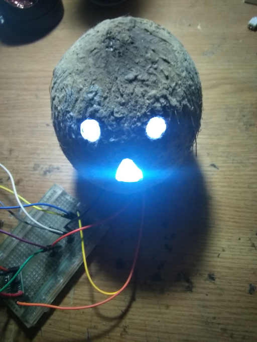
The Tiki Pumpkin idea can be extended by replacing the candle with the LED strip:
That way, the full spectrum of colors would be available.
Scaling up With Logic-Level MOSFETs
The 2N3904 is capable of switching between  to
to  of power which is fairly limiting the dimension of the light strip that can be attached to a few meters at best. A better solution is to use a power MOSFET such as a logic level MOSFET that will extend the possible range of the LED light strip.
Looking at the IRL540 datasheet, particularly to the "Gate-to-Source Voltage"  :
:
it can be observed that a voltage input level in the range of ![Math $[0, 3.3]V$](/lib/exe/fetch.php?media=wiki:latex:/img8112a1ac1ba3d2624f13c93ca002d2f9.png) will turn on the transistor well-enough, especially since at
will turn on the transistor well-enough, especially since at  the
the  curve reaches the apex of the logarithmic curve. Furthermore, looking at the Y axis, the transistor seems to be capable of switching over
  of power which would allow for a longer LED light strip. This means that the
 IRL540 is perfectly suited for controlling an LED light strip and can be used to replace the 2N3904 transistors.
For the contact, copyright, license, warranty and privacy terms for the usage of this website please see the contact, license, privacy, copyright.


