Table of Contents
About
Dataflow programming is frequently used to connect various IoT components due to the robustness and the low entry knowledge requirements. Given a set of inputs, various programming blocks are used to transform the input in order to obtain a desired output. Similarly, various electronic components can be controlled elegantly without having to know a programming language in particular and just relying on programming concepts and logic.
There is a certain equivalence between IoT hardware and the dataflow programming where it feels that the software can act as a stand in for various hardware components thereby accomplishing with software what cannot be done with hardware. The following page attempts to implement various hardware components with their software counterparts. The examples provided use node-red as the dataflow programming language but restricts the set of nodes used to the built-in nodes without requiring additionally dependencies.
Dataflow Programming and Node-Red
One of the particularities of Node-Red is that it is considered to be a non-functional language but rather a flow based language. Nevertheless, each node type can be seen as a function that takes an input, transforms the input and yields an output. Unfortunately, there are no built-in nodes that can take two separate and distinct inputs or parameters in case the nodes are seen as functions.
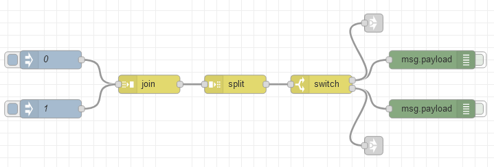
One way to implement a function with two inputs in Node-Red using just the built-in nodes is to use the join, split and switch nodes:
The join node is set to join the input messages after two messages and to output an array containing both messages. The split node takes the array from the join node and outputs two separate messages. Finally, the switch node will receive both messages and route one message through the first output and the second message through the second output.
In other words, injecting 0 or 1 via the injector nodes will store the number 0 or 1 in a buffer inside the join node and will not pass any message further. When another 0 or 1 is injected, the join node will take both numbers and construct an array and output both the previously stored message and the current message.
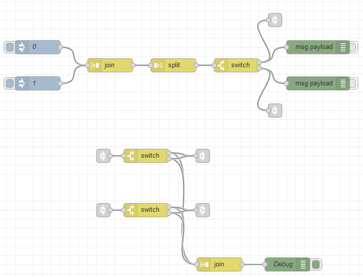
Extending the flow and adding a summator via join node, the Debug node will show the sequence that has been input using the On and Off injectors. The corresponding Node-Red flow is the following:
[{"id":"c8ce7877.104db8","type":"tab","label":"Two-Way Signal Generator","disabled":false,"info":""},{"id":"c803d77a.13909","type":"inject","z":"c8ce7877.104db8","name":"0","topic":"","payload":"0","payloadType":"str","repeat":"","crontab":"","once":false,"onceDelay":0.1,"x":250,"y":140,"wires":[["82efc519.1391a"]]},{"id":"82efc519.1391a","type":"join","z":"c8ce7877.104db8","name":"","mode":"custom","build":"array","property":"payload","propertyType":"msg","key":"topic","joiner":"\\n","joinerType":"str","accumulate":false,"timeout":"","count":"2","reduceRight":false,"reduceExp":"","reduceInit":"","reduceInitType":"num","reduceFixup":"","x":410,"y":180,"wires":[["c542c792.1af738"]]},{"id":"ff23b2ab.867078","type":"debug","z":"c8ce7877.104db8","name":"","active":false,"tosidebar":true,"console":false,"tostatus":false,"complete":"payload","targetType":"msg","x":870,"y":140,"wires":[]},{"id":"8187e6d.1ee6a98","type":"switch","z":"c8ce7877.104db8","name":"","property":"payload","propertyType":"msg","rules":[{"t":"index","v":"0","vt":"num","v2":"0","v2t":"num"},{"t":"index","v":"1","vt":"num","v2":"1","v2t":"num"}],"checkall":"true","repair":false,"outputs":2,"x":690,"y":180,"wires":[["ff23b2ab.867078","89cc481b.75eee8"],["1a683ada.ce11b5","c06f647a.9ffa5"]]},{"id":"c542c792.1af738","type":"split","z":"c8ce7877.104db8","name":"","splt":"\\n","spltType":"str","arraySplt":1,"arraySpltType":"len","stream":false,"addname":"","x":550,"y":180,"wires":[["8187e6d.1ee6a98"]]},{"id":"1a683ada.ce11b5","type":"debug","z":"c8ce7877.104db8","name":"","active":false,"tosidebar":true,"console":false,"tostatus":false,"complete":"payload","targetType":"msg","x":870,"y":220,"wires":[]},{"id":"9be84f14.749cc","type":"inject","z":"c8ce7877.104db8","name":"1","topic":"","payload":"1","payloadType":"str","repeat":"","crontab":"","once":false,"onceDelay":0.1,"x":250,"y":220,"wires":[["82efc519.1391a"]]},{"id":"2ccce841.f94e08","type":"switch","z":"c8ce7877.104db8","name":"","property":"payload","propertyType":"msg","rules":[{"t":"eq","v":"0","vt":"str"},{"t":"eq","v":"1","vt":"str"}],"checkall":"true","repair":false,"outputs":2,"x":490,"y":380,"wires":[["45b8f833.dbe3a8","1497c3c6.9b6444"],["45b8f833.dbe3a8","1497c3c6.9b6444"]]},{"id":"17681165.be2ea7","type":"switch","z":"c8ce7877.104db8","name":"","property":"payload","propertyType":"msg","rules":[{"t":"eq","v":"0","vt":"str"},{"t":"eq","v":"1","vt":"str"}],"checkall":"true","repair":false,"outputs":2,"x":490,"y":500,"wires":[["45b8f833.dbe3a8","50e6af25.b3eb28"],["45b8f833.dbe3a8","50e6af25.b3eb28"]]},{"id":"938619c2.c70f28","type":"debug","z":"c8ce7877.104db8","name":"Debug","active":true,"tosidebar":true,"console":false,"tostatus":false,"complete":"payload","targetType":"msg","x":802,"y":620,"wires":[]},{"id":"45b8f833.dbe3a8","type":"join","z":"c8ce7877.104db8","name":"","mode":"auto","build":"string","property":"payload","propertyType":"msg","key":"topic","joiner":"\\n","joinerType":"str","accumulate":false,"timeout":"","count":"","reduceRight":false,"reduceExp":"","reduceInit":"","reduceInitType":"","reduceFixup":"","x":652,"y":620,"wires":[["938619c2.c70f28"]]},{"id":"89cc481b.75eee8","type":"link out","z":"c8ce7877.104db8","name":"","links":["e15b9b17.7cdf8"],"x":775,"y":80,"wires":[]},{"id":"e15b9b17.7cdf8","type":"link in","z":"c8ce7877.104db8","name":"","links":["89cc481b.75eee8"],"x":395,"y":380,"wires":[["2ccce841.f94e08"]]},{"id":"c06f647a.9ffa5","type":"link out","z":"c8ce7877.104db8","name":"","links":["a028e9ab.51798"],"x":775,"y":280,"wires":[]},{"id":"a028e9ab.51798","type":"link in","z":"c8ce7877.104db8","name":"","links":["c06f647a.9ffa5"],"x":395,"y":500,"wires":[["17681165.be2ea7"]]},{"id":"1497c3c6.9b6444","type":"link out","z":"c8ce7877.104db8","name":"","links":["4c8c5fdb.895498","8b243922.dfbb8"],"x":615,"y":380,"wires":[]},{"id":"50e6af25.b3eb28","type":"link out","z":"c8ce7877.104db8","name":"","links":["6431faf4.6ee1fc"],"x":615,"y":500,"wires":[]}]
Irrespective of the summator and the debug output, the output from the injectors can be used to feed logical gates with two inputs where the 0 and 1 nodes are used to select the input of the logical gate.
Transistor as A Switch
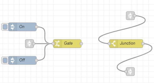
Given a signal present on the base input of a transistor, current flows between the emitter and collector. One possible way to implement a transistor using dataflow programming is to consider that the polarization achieved when applying voltage to the base of the transistor is a state element and that depending on the input signal the state can be toggled. Depending on the state, messages can be made to flow across the junction.
The illustration depicts two message pumps labeled On and Off and a node-red change Gate node that is responsible for setting a variable global to the current flow. The Junction node is a switch node that will only pass messages in case the global state variable is set to on.
The complete Node-Red flow export can be imported from the following code:
[{"id":"31b880c2.d17f98","type":"tab","label":"Transistor","disabled":false,"info":""},{"id":"aba20727.5f9e48","type":"inject","z":"31b880c2.d17f98","name":"On","topic":"","payload":"1","payloadType":"num","repeat":"","crontab":"","once":false,"onceDelay":0.1,"x":310,"y":200,"wires":[["3235318d.8e4376"]]},{"id":"3235318d.8e4376","type":"change","z":"31b880c2.d17f98","name":"Gate","rules":[{"t":"set","p":"gate","pt":"flow","to":"payload","tot":"msg"}],"action":"","property":"","from":"","to":"","reg":false,"x":470,"y":260,"wires":[[]]},{"id":"dd07e8cd.30666","type":"switch","z":"31b880c2.d17f98","name":"Junction","property":"gate","propertyType":"flow","rules":[{"t":"eq","v":"1","vt":"num"}],"checkall":"true","repair":false,"outputs":1,"x":680,"y":260,"wires":[["7210792e.bf936"]]},{"id":"eff867c2.e3bb8","type":"inject","z":"31b880c2.d17f98","name":"Off","topic":"","payload":"0","payloadType":"num","repeat":"","crontab":"","once":false,"onceDelay":0.1,"x":310,"y":320,"wires":[["3235318d.8e4376"]]},{"id":"7210792e.bf936","type":"link out","z":"31b880c2.d17f98","name":"","links":[],"x":695,"y":360,"wires":[]},{"id":"cc29556f.bb437","type":"link in","z":"31b880c2.d17f98","name":"","links":[],"x":695,"y":160,"wires":[["dd07e8cd.30666"]]},{"id":"d6a5fc8f.e5d188","type":"link in","z":"31b880c2.d17f98","name":"","links":[],"x":335,"y":260,"wires":[["3235318d.8e4376"]]}]
A basic transistor is all that is needed in order to create further logic gates.
AND
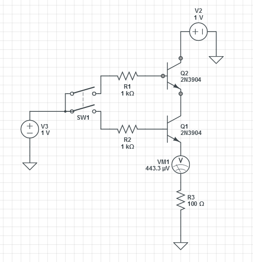
Chaining the collector and emitters of two transistors will result in an AND gate where the two inputs will be the base of each transistor and each junction will allow current to flow depending on the input signal at the base of each transistor.
A simple circuit would look like the following:
where the switch SW1 is a DPST switch that will set the base to high on both transistors. There are four cases given the illustrated circuit that are relevant depending on whether a signal is present at each of the transistor bases:
 |  | Voltage |
|---|---|---|
| off | off |  |
| off | on | |
| on | off | |
| on | on |  |
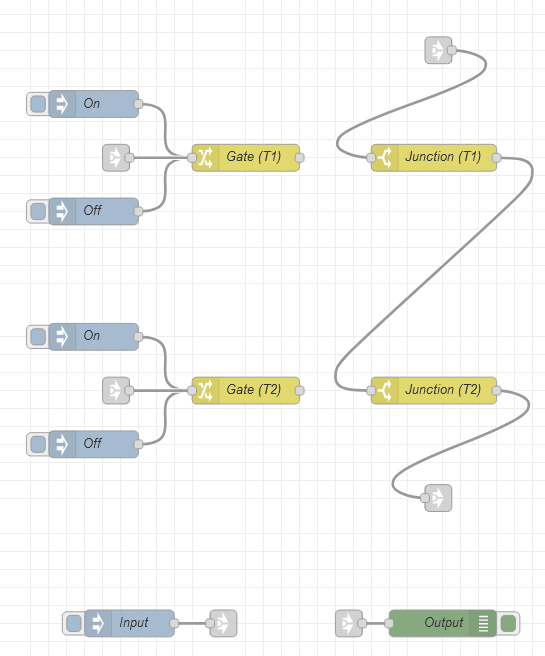
Using the transistor from the previous section, a node-red flow can be built to simulate an AND gate which is very similar to the electronic circuit.
The injectors On and Off are used for convenience in order to set the state for each base of each transistor. The Junction nodes are set in series and whenever the state is set to On for both transistor gates, messages can flow between the junction nodes.
Here is the node-red flow for an AND gate created by placing two transistors in series:
[{"id":"70cfcafb.1be4c4","type":"tab","label":"AND Gate","disabled":false,"info":""},{"id":"b2838b74.550df8","type":"inject","z":"70cfcafb.1be4c4","name":"On","topic":"","payload":"1","payloadType":"num","repeat":"","crontab":"","once":false,"onceDelay":0.1,"x":310,"y":220,"wires":[["8e0492e1.d36a58"]]},{"id":"8e0492e1.d36a58","type":"change","z":"70cfcafb.1be4c4","name":"Gate (T1)","rules":[{"t":"set","p":"gate_t1","pt":"flow","to":"payload","tot":"msg"}],"action":"","property":"","from":"","to":"","reg":false,"x":480,"y":280,"wires":[[]]},{"id":"b8bcad.f9ad2b5","type":"switch","z":"70cfcafb.1be4c4","name":"Junction (T1)","property":"gate_t1","propertyType":"flow","rules":[{"t":"eq","v":"1","vt":"num"}],"checkall":"true","repair":false,"outputs":1,"x":690,"y":280,"wires":[["3999cfb1.5e3d1"]]},{"id":"a6516782.a2db38","type":"inject","z":"70cfcafb.1be4c4","name":"Off","topic":"","payload":"0","payloadType":"num","repeat":"","crontab":"","once":false,"onceDelay":0.1,"x":310,"y":340,"wires":[["8e0492e1.d36a58"]]},{"id":"3a7b8a70.78b38e","type":"inject","z":"70cfcafb.1be4c4","name":"Input","topic":"","payload":"","payloadType":"date","repeat":"","crontab":"","once":false,"onceDelay":0.1,"x":350,"y":800,"wires":[["848d1b51.5b2a88"]]},{"id":"51a8d50e.75fd5c","type":"inject","z":"70cfcafb.1be4c4","name":"On","topic":"","payload":"1","payloadType":"num","repeat":"","crontab":"","once":false,"onceDelay":0.1,"x":310,"y":480,"wires":[["d942f9c5.1f768"]]},{"id":"d942f9c5.1f768","type":"change","z":"70cfcafb.1be4c4","name":"Gate (T2)","rules":[{"t":"set","p":"gate_t2","pt":"flow","to":"payload","tot":"msg"}],"action":"","property":"","from":"","to":"","reg":false,"x":480,"y":540,"wires":[[]]},{"id":"5af40f19.c8141","type":"inject","z":"70cfcafb.1be4c4","name":"Off","topic":"","payload":"0","payloadType":"num","repeat":"","crontab":"","once":false,"onceDelay":0.1,"x":310,"y":600,"wires":[["d942f9c5.1f768"]]},{"id":"3999cfb1.5e3d1","type":"switch","z":"70cfcafb.1be4c4","name":"Junction (T2)","property":"gate_t2","propertyType":"flow","rules":[{"t":"eq","v":"1","vt":"num"}],"checkall":"true","repair":false,"outputs":1,"x":690,"y":540,"wires":[["f65644ad.e372d"]]},{"id":"43567898.071ea8","type":"debug","z":"70cfcafb.1be4c4","name":"Output","active":true,"tosidebar":true,"console":false,"tostatus":false,"complete":"true","targetType":"full","x":700,"y":800,"wires":[]},{"id":"4c8c5fdb.895498","type":"link in","z":"70cfcafb.1be4c4","name":"","links":["1497c3c6.9b6444"],"x":335,"y":280,"wires":[["8e0492e1.d36a58"]]},{"id":"6431faf4.6ee1fc","type":"link in","z":"70cfcafb.1be4c4","name":"","links":["50e6af25.b3eb28"],"x":335,"y":540,"wires":[["d942f9c5.1f768"]]},{"id":"f65644ad.e372d","type":"link out","z":"70cfcafb.1be4c4","name":"","links":["9ac898af.0b5008"],"x":695,"y":660,"wires":[]},{"id":"1b7611dc.5b8f46","type":"link in","z":"70cfcafb.1be4c4","name":"","links":["848d1b51.5b2a88"],"x":695,"y":160,"wires":[["b8bcad.f9ad2b5"]]},{"id":"848d1b51.5b2a88","type":"link out","z":"70cfcafb.1be4c4","name":"","links":["1b7611dc.5b8f46","7c3fb96f.94e7a8"],"x":455,"y":800,"wires":[]},{"id":"9ac898af.0b5008","type":"link in","z":"70cfcafb.1be4c4","name":"","links":["f65644ad.e372d"],"x":595,"y":800,"wires":[["43567898.071ea8"]]}]
Using the two message input from the previous section, when clicking the 0 and 1 injectos, the gates of the transitors will either close or open thereby yielding the proper logical AND output.
| Injector | AND |
|---|---|
[0, 0] | 0 |
[1, 0] | 0 |
[0, 1] | 0 |
[1, 1] | 1 |
For the contact, copyright, license, warranty and privacy terms for the usage of this website please see the contact, license, privacy, copyright.
