Table of Contents
About
Standard electrical kettles can be found on the market at a bargain price from different no-name brands. Most of these devices have the same circuitry inside and more or less the same architecture with little to no differences between the no-name brands making the components even interchangeable. Examples of brands include:
- "AFK",
- "GourmetMaxx",
- etc.
Most of these are produced in China and whole-sell for about USD1 or USD2 per 1000 pieces. The kettles then seem to be imported and sold on the European market for about 46 Euros a piece with varying branding - making about 500-700% the profit!
Lovely devices to automate, however!
Requirements
Kettle
There seem to be serveral minor variations on the electronics contained in the mentioned kettles:
- kettles with a rocker switch that spring back whenever a given temperature is reached,
- kettles with a touch-pad using Phillips capacitive springs for the buttons,
- kettles that use momentary push buttons
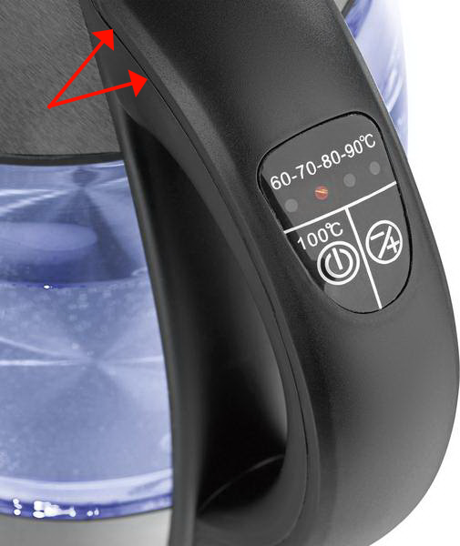
Out of all of them, the last variation is preferred for this mod since they are easier to jerry-rig using a WeMoS board. Kettles that have momentary push buttons look like the following:
and attention should be paid to the control panel on the handle:
There are two buttons shown in the image: the button on the left is meant to start the kettle and boil the water to  , after which the kettle stops and waits to be lifted (there is also a long-press secondary function that keeps the water at boiling temperature for 2 hours), and the button on the right that is meant as a temperature selector that will heat up the water to the selected temperature.
Regardless, the illustrated control panel is ideal for the modification presented in this writeup.
IoT
- a WeMoS D1 mini board,
- a
 AC to
AC to  mini stepdown converter,
 - a bare PCB,
- two
2N3904transistors, - two
 resistors
 - cables and solder equipment
Kettle Teardown and Circuitry
The first place to start dismantling the kettle is the top part of the handle.
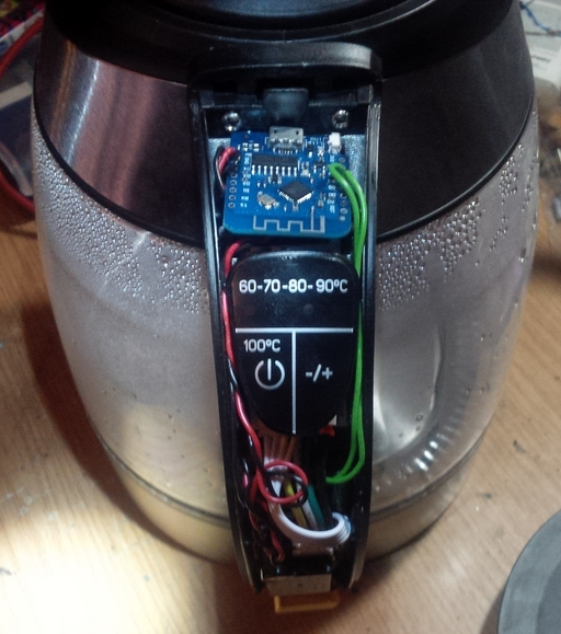
As can be seen from the image, the handle has a crack running all the way around - the handle is not glued just attaches and can be cracked open by inserting a thin screwdriver in the crack and prying the handle open. Some pressure is required but eventually the handle can be opened and the circuitry will be exposed.
The image above shows the exposed circuitry of the handle with a WeMoS D1 mini board already mounted on top. The kettle circuitry is otherwise very simple to grasp:
- the kettle receives power by placing the kettle onto a base connected to the mains,
- the lower part of the kettle contains the heating element and LED lights as well as wires leading up to the handle circuitry,
- the handle circuitry contains a stepdown and power regulator that powers the control panel (the one containing the buttons)
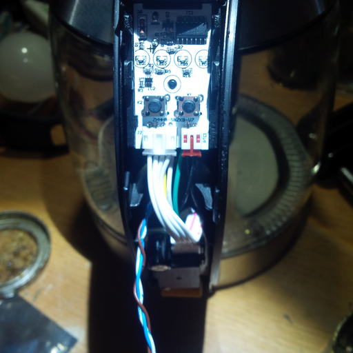
Opening the control panel, the momentary push buttons are revealed:
The button circuitry is simple in design: one pin of the push buttons is common to both buttons are represents the ground, and the other pin for each button is the actual signal that runs to the small IC on the board in order to perfrom the various functions.
Using a multimeter, the buttons can be measured and wire leads attached: one pin should be common to both buttons whilst the other two pins should not be in contact. Looking at the previous image, there is some ethernet cable wire running on the left; three wires, in fact, one being the common ground, the other two wires for the signals.
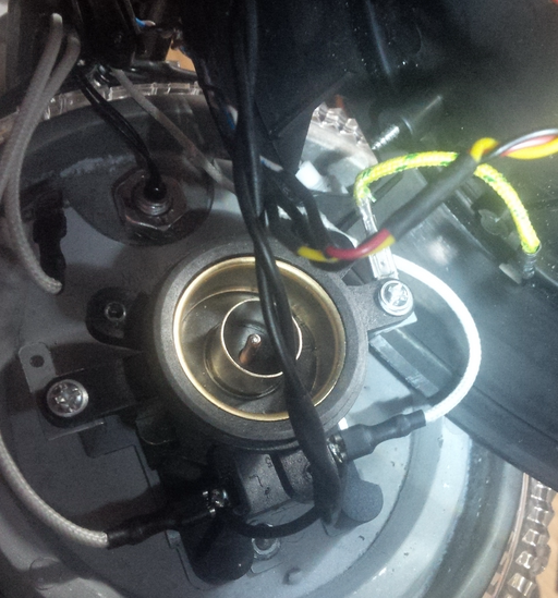
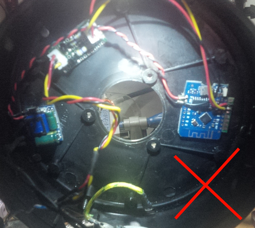
As previously mentioned, the base can be dismantled after the handle is opened and contains the heating element, a grounding wire, some LED leads and a water level sensor for the control panel.
The image above depicts two wires that have been soldered to the  AC contacts in order to draw power for the WeMoS D1 board via the stepdown converter. In a previous attempt, the circuitry had been placed in the bottom base of the kettle and is presented here just as an overview of the entire circuitry but should not be reproduced.
Even though the base seems like the ideal space for the circuitry, the heating element dissipates a lot of heat and the WeMoS board will end up fried.
A much better place for the circuitry is inside the handle along with the rest of the kettle circuitry even though it is a very tight fit.
Block Diagram
An overview of the circuitry as seen from the perspective of the kettle handle in upright position is presented below.
^ Kettle height as seen from the handle
|
|  +------------------+
|  |  WeMoS D1 Mini   |
|  |                  |
|  | 5V GND   GPIO    |
|  +--+-+-----+-+-----+
|     | |     | |
|     | |     | |        +------------------+
|     | |     | |        |   Control Panel  |
|     | |     | |        |                  +<---+
|     | +---------+------+  GND             +<-+ |
|     | |     | | |      |  Button1 Button2 |  | |
|     | |     | | |      +----+--------+----+  | |
|     | |  +--+-+-+-+         |        |       | |
|     | |  | Switch +---------+        |       | |
|     | |  |        +------------------+       | |
|     | |  +--------+                          | |
|     | |                                      | |
|    +| |-                                     | |
|  +--+-+------------+                         | |
|  |  Power Stepdown |                         | |
|  +--+-+------------+                         | |
|     | |                                      | |
|  +--+-+------------+ LED & Heating Control   | |
|  | Kettle Stepdown +<------------------------+ |
|  |                 +<--------------------------+
|  +------+-+--------+ Wires
|         | |
|  +------+-+--------+
|  |  Kettle Mains   |
|  +-----------------+
|
|
+
The reason for adding a second parallel stepdown is that the stepdown included with the kettle is meant to power the control panel with the buttons and does not have sufficient Amperes to drive both the control panel and the WeMoS board.
The Switch Circuit
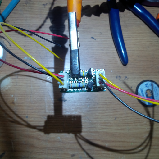
The block named "Switch" is a dual 2N3904 transistor switch with two  resistors. The same circuit is used as for the designing iLO project just that two circuits are placed in parallel for each GPIO pin.
Here is what the switch circuit looks like when assembled:
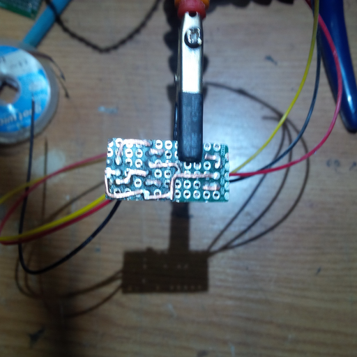
and from the back of the PCB with hand-made traces:
Putting it Together
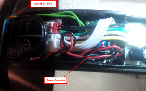
Perhaps the most difficult part is getting everything to fit inside the handle. The WeMoS board on top has no trouble fitting on top and the power converter can be squeezed underneath the cables leading from the kettle power converter to the controller board with the buttons.
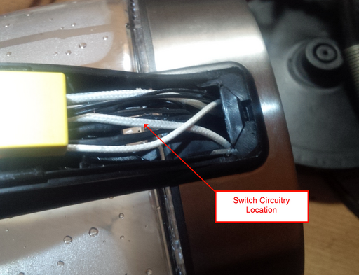
The switch circuit is mounted at the base of the handle since it seems to fit best:
All components are well cramped inside such that small gauge wires should be used: IDE ribbon cable wires or ethernet twisted wires perhaps - although the latter are rigid and tough to slide in place.
Programming the WeMoS Board
With the hardware part done, the rest is a matter of adding a GPIO toggler to the WeMoS board. A boilerplate pin toggling template can be used to make the WeMoS maintain a connection to a Wifi network and additionally subscribe to an MQTT topic.
Controlling the Kettle
Depending on which GPIO pins have been used, the kettle can be controlled from the command-line (or later, via Node-Red).
For instance, in case GPIO pin 6 was connected to the left-most button, the following command:
mosquitto_pub.exe -h 172.16.1.1 -t 'esp/kettle' -m '{ "pin": 6, "state": "on" }' && \\
    sleep 0.10 && \\
    mosquitto_pub.exe -h 172.16.1.1 -t 'esp/kettle' -m '{ "pin": 6, "state": "off" }'
should make the WeMoS board set pin 6 to HIGH, sleep for  and then set pin
 6 to LOW effectively emulating a button press. The same would apply for the other button, just that the pin number should differ.
In case the previous command did not work, there are a few hardware points of failure to check:
- the
2N3904transistors are fairly brittle and excess heat (as it happened in the first attempt) can damage the transistors badly. Measure conductance between the emitter and the base: if there is any conductance then most likely the transistor is busted. - for the switch circuit, make sure that common ground connects straight through and that the GPIO signals are not shorted.
- the boilerplate pin toggling template will log to the serial port (USB, if connected to a computer) all MQTT messages received and which GPIO pin has been toggled.
Automating via Node-Red
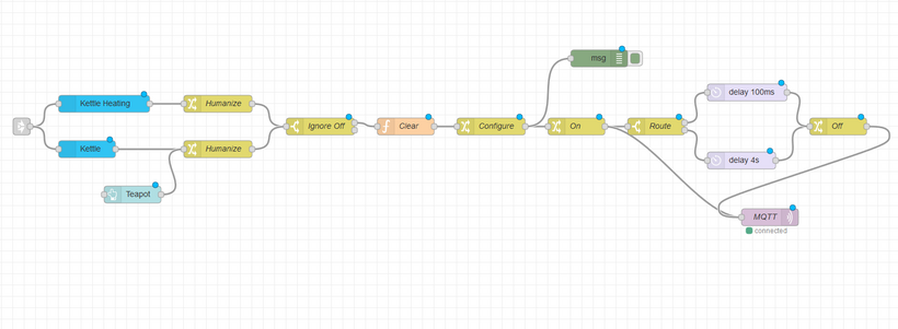
A node-red flow could look like the following:
From left to right:
- the entry point is a cross-flow connector that leads from an Amazon Alexa HUB to the current flow into two separate devices: "Kettle Heating" and "Kettle". Whilst "Kettle Heating" emulates the left-button 2-second long-press, the "Kettle" device will just switch the kettle on. These are two separate devices that can be toggled individually by saying: "Alexa, turn kettle heating on", respectively "Alexa, turn Kettle on",
- the nodes marked "Humanize" is some internal node-red syntactic sugar that pins a more literal name to the "Kettle Heating" and "Kettle" nodes since Node-Red uses a device ID hash - this node is not that relevant but it is used later on for the node marked "Route" to distinguish between the devices,
- the "Ignore Off" node, just grounds the commands "Alexa, turn Kettle Heating off" respectively "Alexa, turn Kettle off" because the buttons on the kettle are push-buttons with no feedback. In other words, "on" works the same way as "off" - ideally, the "off" signal would be routed to some memorization or persistance Node-Red module in order to memorize the state of the kettle.
- the "Clear" node just flushes
msg.payload, - the "Configure" node will set the MQTT topic and
msg.payload.pinto the pin used for the button to be pressed, - the "On" node sets
msg.payload.statetoon- the message is now sent to MQTT, for instance:{ "pin": 6, "state": "on" }and a copy of the message is passed on to the "Route" node. - the "Route" node, based on the "Humanize" nodes at the start now either pauses for
 for the "Kettle" device (ie: when "Alexa, turn on kettle" is spoken), or pauses for
  for the "Kettle Heating" device (ie: when "Alexa, turnon kettle heating" is spoken).
 - the "Off" node just switches "msg.payload.state" from "on" to "off" and passes the message to MQTT, for instance:
{ "pin": 6, "state": "off" }.
In effect, the flow after and including the "On" node will distinguish between a short press on the left-most button on the kettle and a long-press on the left-most button on the kettle.
For the contact, copyright, license, warranty and privacy terms for the usage of this website please see the contact, license, privacy, copyright.


