Table of Contents
About
One of the major annoyances with digital multimeters is that they have an LCD with an extra backlight button that will light up the LCD only for a few seconds. Most of the time when working, the LCD is barely visible and it always makes one wonder why these multimeters do not have a simple switch to permanently turn the backlight on.
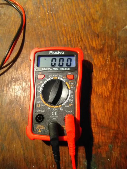
This page shows a modification to a generic multimeter ("Plusivo") where the backlight button will be removed completely and the backlight turned permanently on when the multimeter is on. Bear in mind that not all multimeters are the same, and it just so happened that the cheap "Plusivo" mentioned on this page is designed to maintain the backlight if the backlight button is held down.
Requirements
- soldering equipment,
- magic sculp (two-part resin and amine epoxy putty) - these are truly magic!,
- another multimeter would help to measure contacts,
- black nail polish or black paint
Modification
The Plusivo is a rather generic multimeter with the usual features found on all other multimeters. When held down, the top left button will turn on the LCD backlight and maintain it as long as the button is pressed. This offers an opportunity to disassemble the multimeter and short out the button in order to make the backlight stay on. The extra bonus is that the backlight is additionally controlled by the rotor switch that, when turned to the off position will also cut the backlight.
Disassembling the Plusivo is straightforward. Just two screws along the bottom part of the multimeter will simply release the entire shell.
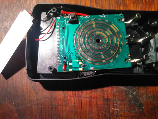
Similarly, the PCB can be released by tapping out a few more screws. With the PCB turned flip-side, the upper side of the PCB can be seen.
In the image, the button closest to the viewer is the backlight button. It was determined that it would only be sufficient to short the top-most pins in order to keep the backlight on. However, just to be complete, it was decided to go the full mile and remove the button as well as seal the hole left over in the multimeter chassis.
Armed with some soldering wick and solder iron, the four pins of the push button are cleaned and the button slid off the PCB revealing four pretty pads underneath the button. Using some copper wire, the top pads are connected together. The rotor is just temporarily fitted on top of the contacts, just to check that the backlight turns on.
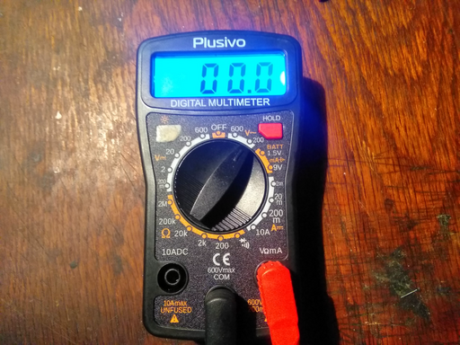
Assembling the multimeter back together, the rotor is switched to any position in order to check that the backlight turns on. Conversely, the rotor is switched to the off position to ensure that the backlight goes off when the multimeter is turned off.
The empty hole left over after removing the button is then filled with "Magic Sculp", a resin and amine two-part epoxy that will harden in one day. The final touches will be to use some black paint (perhaps nail polish) to cover up the button and make it look seamless.
Job well done! 
Closing
As mentioned previously, not all multimeters are the same such that modifying them will vary. In any case, it is very strange that nobody thought about just having a very basic flip switch since the LCD screen is completely unreadable and very annoying to read even if sufficient light is provided.
For the contact, copyright, license, warranty and privacy terms for the usage of this website please see the contact, license, privacy, copyright.


