Table of Contents
About
Antec PSUs are relatively low-cost, solidly built and provide a budget alternative to more expensive PSUs in the same category. Segotep RGB fans and LED strips are also budget alternatives to more expensive brands but if handled correctly they can be a great and alluring substitute.
One shortcoming of the Antec PSUs is that they lack an RGB fan - in fact, even high brand PSUs rarely have a fitted RGB fan. The Antec PSU fans usually shine a monochromatic color - mostly white and have a switch that allows turning the LED off.
These notes provide some guidelines for modifying an Antec PSU by fitting a Segotep RGB fan thereby providing an uniform color for any PC case whilst minding a moderate budget.
Requirements
- Segotep Halo Ring RGB 120mm Three fan kit - the fitted RGB lighting system (USD50),
- Segotep Pro Vibrant 120mm RGB Fan - the RGB fan that will be fitted into the PSU (USD15),
- Antec EDG550, fully modular PSU, 80PLUS GOLD, 550W, EDGE Series - the PSU that will be retrofitted with an RGB fan (USD100).
Instructions
Dismantling the Antec PSU is pretty straightforward: there are four screws holding the PSU together and can be easily accessed. One of the screws is covered with a warranty seal that can be removed for the procedure thereby, most likely, voiding the warranty. The PSU then opens in two parts - one part hosts a simple 140mm fan with two pairs of leads running to the other part of the PSU. The four leads on the Antec PSU would indicate a PWM fan where a pair of leads run to +12VDC and GND whilst the other pair of leads are PWM and SENSE.
The Segotep Pro Vibrant 120mm RGB Fan unfortunately does not have that many leads such that only the +12VDC, GND will be connected to power the fan. On the other hand, the Pro Vibrant 120mm RGB Fan has the RGB cable which seems to be a standard PSU RGB cable with 6 pins: +12VDC, and R, G and B.
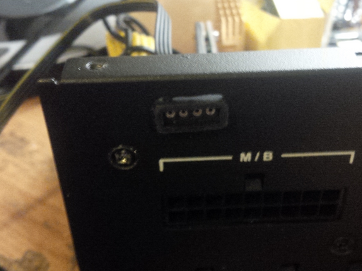
To fit the RGB lead nicely and additionally maintain the modularity of the Antec PSU, an aperture is drilled using a Dremel into the chassis of he PSU right above the MBU connector (the proprietary 18-pin ATX equivalent power connector).
A JB weld compound is then mixed together in a thick paste that will be used to glue the RGB connector from the fan to the chassis of the PSU.
The compound will need about an hour to dry before being able to continue the project.
Now the connector is welded to the PSU case and provides just enough of an opening to be able to connect an RGB motherboard cable.
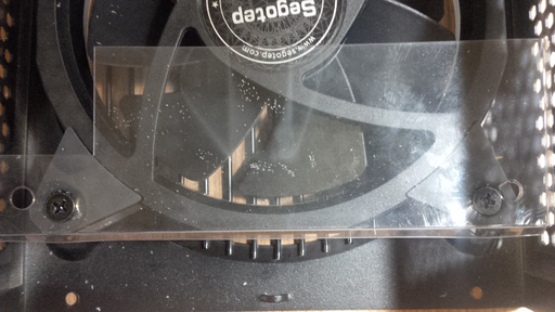
Since the Segotep Pro Vibrant 120mm RGB Fan is only 120mm in diameter and the Antec fitted fan is 140mm in diameter, new holes have to be drilled after removing the Antec fan.
The Antec PSU also has a plastic shield fitted that most likely is meant to protect the fan from the cables underneath. Since the Segotep fan is smaller, new holes have to be drilled into the plastic shield.
With the fan fitted to one side of the PSU and the connector welded to the other side of the PSU, the cables can be organized and the +12VDC and GND can be connected between the PSU PCB and the fan.
The PWM and SENSE signals are left open since there are no such leads on the Segotep fan. Fortunately, there is some space between the PSU PCB and the front connectors allowing the fan cables to be nicely tucked in-between without interfering with the fan operation.
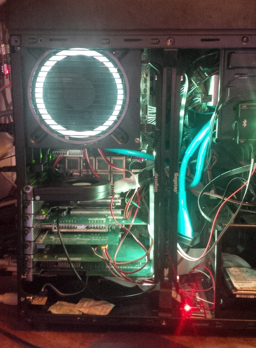
Assembling the PSU, fitting inside the PC case, and hooking up the RGB connector, the fan lights up properly and matches the colors on the other fans and light strips. The fan and already existing lighting elements are checked via the bluetooth application to make sure that the proper RGB values are set when changing the colors.
Notes on RGB and Fan / Lighting Strip Controllers
The instructions above apply to cases where the motherboard has RGB capabilities. In this particular case, the motherboard did not have any RGB connectors such that the fan was connected directly to the controller by splicing Dupont cables with spare RGB connectors.
Fortunately, the Segotep Pro Vibrant 120mm RGB Fan is delivered with two RGB connectors: male and female (on the same lead), such that the female RGB connector can be welded to the PSU chassis whilst the male RGB connector can be sliced off and used to create a cable that will connect to the Segotep controller.
The wiring had to be deduced using a multimeter since not many sources are available on the internet. The following ASCII depiction shows an RGB socket on the Segotep controller annotated with the meaning of each lead:
      +--------+
+--+--+--+--+--+--+--+
|  *  *  *  *  *  *  |
+--|--|--|-----+--|--+
   |  |  |        |
   |  |  |        |
   |  |  |        |
   +  +  +        + +12VDC
   G  R  B
It seems that RGB connector has 4 leads, one of which is the +12VDC which is mandatory, regardless whether the fan is already powered with +12VDC for spinning. The additional +12VDC lead on the RGB connector probably drains through the R, G and B leads (using resistors as a combining function?) in order to achieve the combined RGB effect.
By slicing the male connector off the Segotep Pro Vibrant 120mm RGB Fan and using some Dupont wires, a cable can be created that connects from the Segotep controller and to the newly mounted female connector on the PSU.
For the contact, copyright, license, warranty and privacy terms for the usage of this website please see the contact, license, privacy, copyright.


