Table of Contents
About
The Anki Vector robot is a nice desktop robot with a number of crucial flaws; one of the flaws, amonst many, is that the Vector has issues navigating in low light situations. The Vector camera is unable to see in darkness and the robot will sometimes hit the ground with its lift and then make its eyes very large - admittedly, using the light from its own eyes like car lights to be able to see into the distance. More than often (always?) the additional lights from its eyes is insufficient and the Vector is unable to navigate to its charger thereby ending up stranded with its battery depleted.
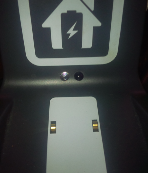
The following tutorial describes an Anki Vector mod that will solve the low-light issue and allow the Vector to navigate to its charger even in pitch-darkness. Overall, the mod implies a modification to the base, in order to install a proximity sensor and pull an USB line on the outside such that an USB light can be connected to the base. In doing so, whenever Vector leaves its craddle, the proximity sensor will trigger and the USB light will go on, thereby illuminating the surroundings and, implicitly, the "home pattern" drawn onto the base that Vector needs to see in order to dock.
TL;DR we're going to hook up a proximity triggered lamp as part of the craddle such that Vector can see the base when it's dark
Demonstration
Requirements
- one 5V infrared analog (not digital!) proximity sensor - these are mostly very cheap and the functioning principle is that light emitted from one diode is supposed to bounce back off an object such that it will be picked up by the other diode. The rest of the circuitry on the board acts as an inverse latch-switch where current flows from the pin marked
VCCto the pin markedOUTwhen no object can be detected. Respectively, whenever an object is detected, the circuit betweenVCCandOUTis interrupted - which is what is needed, turn on the light when Vector is not in the craddle.
Note that there are some IR sensors with 4 pins - those sensors are digital sensors, they will raise the voltage along a square signal (ie:  for on,
  for off, etc.) They can be used in conjuction with, say an embedded system with GPIO (Rasbperry Pi, NodeMCU, etc.) pins but the purpose of this project was to keep the circuitry as simple as possible.
- micro-USB port - the port will be mounted on the back of the base and will conveniently offer 5V output whenever Vector is not on the craddle.
- some nice desk lamp - for the preliminaries of the project, a cheap, flexible USB light was chosen similar to the one in the image below. However, feel free to be creative: perhaps an USB desk lamp in the shape of Mars alluding to a lander, etc...
- tools: dremel, soldering equipment, wires, micro USB to USB adaptor (if you want to power a desk lamp with an USB-A type connector)
Circuit Design
Since an analog 5V IR sensor will be used, there will not even be a need for a transitor to bump up the voltage. The 5V sensor will act as a relay or a latch and will just pass through the voltage that it is fed at its VCC pin to the OUT pin. Naturally, since the IR sensor is meant for micro-electronics, it will probably not be able to pass a large amount of current, nor do USB ports powering the Vector craddle have too high of an amperage ( to
to  , at best).
The following block diagram should explain how the various components will be connected together:
                    +-----------------+
                    | Infrared Sensor |
                    +-----------------+
                    Vcc| Gnd| Out|
                       |    |    |
                       |    |    |
                       |    |    |
+--------+ 5V          |    |    |     5V +---------+
| Vector +-------------+    |    +--------+  Micro  |
|  Base  +------------------+-------------+   USB   |
+--------+ Gnd                            +---------+
Assembly
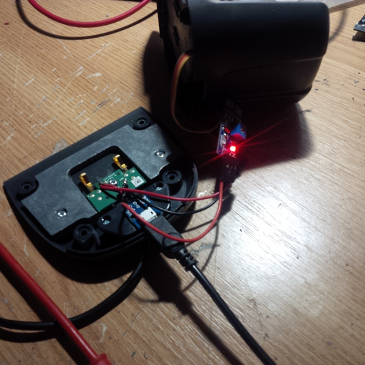
The problem with the 5V IR sensor is that it is rather large and will not fit inside the base without desoldering the two IR LEDs from the PCB. The LEDs can be desoldered and connected with a slice of 4-way ribbon cable to the PCB. Then, the IR sensor circuitry can fit inside the base by sliding it inside the hollow back.
Once the IR LEDs have been desoldered from the PCB and connected via a ribbon cable to the IR PCB, two holes must be drilled strategically into the Vector craddle. Perhaps the best spot to place the LEDs is just underneath the "home symbol". Under any circumstance, the home symbol and the white paint on the craddle should not be tampered with - it is used by Vector to detect the base and to align properly so Vector can back up onto the craddle and recharge.
The micro-USB port is mounted at the back of the base by cutting a plastic hole just enough to be able to connect a micro USB cable or micro USB to USB-A adaptor.
The micro USB port itself has been glued on the inside of the craddle such that it does not move when a device is connected to the port.
Issues and Further Work
Vector's case is black and is thus not a proper reflective surface. Fortunately, the IR sensor circuitry contains a potentiometer that can adjust the sensitivity. Too much sensitivity and the IR sensor will detect Vector as it is looking at the craddle and the light will be switched off, too little sensitivity and the IR beam will not bounce back off Vector's surface and the light will never go off.
One solution is to put a sticker on the back of Vector (out of a white or shiny material) thereby making the surface that the IR sensor uses more reflective. Then, using the potentiometer and Vector cradled, adjust till the light goes off.
Alternatively, echo-location / radar could be used instead. The problem is that even to this date, the radar sensors are rather large - to be understood that  has to be considered "large" in terms of Vector's micro-architecture. Ultimately, the sensor does not really have to be integrated into the Vector base, such that a separate device can be made using echo location and placed next to Vector's base.
A simple photo-diode can be used instead of proximity detection to just turn on the light when it is sufficiently dark. However, if that were to be done, there would be not much of a difference to getting a dark-triggered desk lamp and not even touching the Vector at all.
Ultimately, perhaps, as further work, some of these ideas could be combined into a more complex circuit and use a more involved logic to determine when the light should be turned on or off.
For the contact, copyright, license, warranty and privacy terms for the usage of this website please see the contact, license, privacy, copyright.


