Table of Contents
About
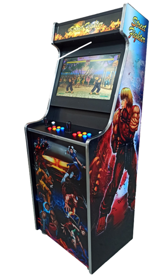
A recent acquisition of an arcade cabinet got us thinking whether the design could be in some way improved or enhanced given recent technological developments.
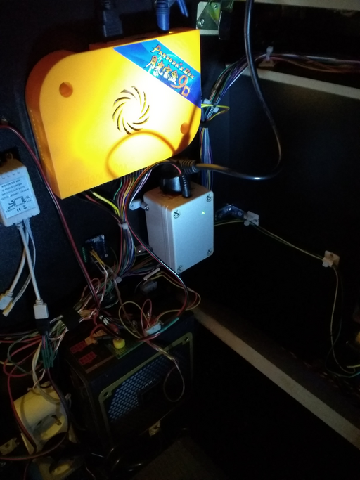
The hardware configuration of the acquired cabinet is the following:
- PandoraBox jamma connector machine,
 power supply,
- HDMI and VGA LCD screen, PandoraBox connecting via HDMI to the LCD
- white lighting on the bottom of the arcade cabinet,
- two speakers on the front of the cabinet, with small amplifier and volume control connected to the LCD screen headphones output,
- single-slot configurable coin acceptor,
- 3 slot plug extender,
- zip ties used to keep cables tied together
and the goal is to improve the quality of the cabinet.
Planned Changes
The following changes are planned:
- replace the speakers with more powerful speakers, and/or add more speakers, preferably with a more powerful amplifier,
- use IoT technology to add props to the cabinet,
- reverse-engineer the PandoraBox or replace with a PC or Raspberry Pi for more games,
- replace the lighting on the bottom of the arcade cabinet with an RGB controller and add lighting to the back of the cabinet
and will involve a few changes to the overall structure of the cabinet wiring.
Redesigning the Power Supply
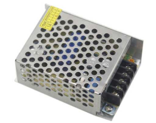
Since more hardware will be added or hardware will be replaced with more powerful counterparts, the first step would be to replace the stock power supply with a more powerful power supply. The stock power supply is a typical  voltage regulated switching power supply:
The power supply hooks up to the plug extender and provides power to the circuitry in the cabinet via  and
and  terminals. Aside the power-supply, the LCD screen is separately fed via its own plug from the plug extender such that the power supply is not involved in providing power to the LCD. The terminals on the power supply use screws to hold down the wires in place such that leads can be removed using a screwdriver.
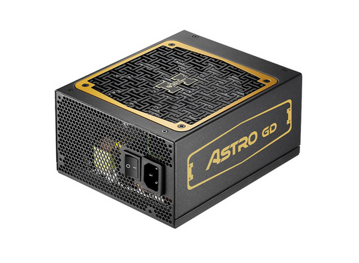
That being said, the power supply has to be removed and replaced with a more powerful power supply. A very good choice is a PC power supply. Albeit more expensive, a relatively cheap PC power supply is naturally of better quality, tweaked to regulate power to PC with extra protections in place to protect sensitive circuitry.
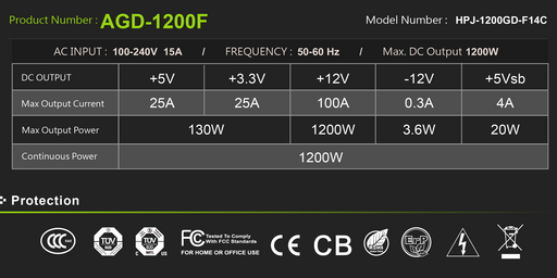
A Sirtec AGD-1200F power supply rated at  was chosen for the project:
mainly because it is capable of outputting a large number of amperes ( ) on the
  line.
line.
When buying PC power supplies for custom projects it is important to be able to see the label (and unfortunately, many shops do not clearly show the power distribution label) in order to be able to determine the maximal amount of power that could be drawn off each line.
Knowing that an amplifier will be fitted into the cabinet, rated at about  and knowing that a car amplifier will be used, then the
  line on the power supply should be capable of outputting at least
  .
.
The Sirtec AGD-1200F seems to be perfectly capable of handling the power requirements and is relatively cheap compared to Corsair power supplies.
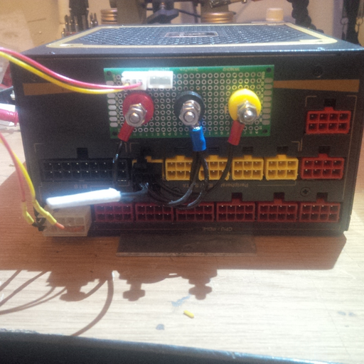
Since the Sirtec AGD-1200F is a fully modular power supply, one option would have been to cut the wires and replace the shoe connectors with molex connectors but since the overall design of the cabinet has to be preserved, the power supply has been modified instead by adding a PCB board with connectors.
The PCB is held in place on the power supply using double-sided strong 3M sticky tape. A power supply connector is cut, the voltage on the leads are measured and the wires are fitted with shoe / ring connectors and fit on the terminals attached to the PCB. The terminals themselves are standard jack terminals that have been cut using a Dremel to only preserve the main shaft and the washers such that the wires can be fastened down.
One problem appears to be that each power line, both the  and the
  have disjunct grounding leads but it is safe to connect them both to the central terminal on the PCB to act as a common ground. Ideally though, all the equipment using
  would should use the
  grounding wire separately from the
  circuitry for better isolation.
Two additional leads are pulled (on the bottom left) from the PS_ON and a ground pin and connected on the PCB to a white lead connector. The white lead connector on the upper-left of the PCB is connected 1-to-1 to the white connector immediately next to it. The connector can then be fitted with two wires and the power supply can then be turned on or off just by making contact between the two extreme pins. The extra addition of the white connectors has been made with IoT in mind because the two wires can be controlled via an Arduino GPIO pin.
The stock power supply had holes drilled into the bottom plate and was held in-place on the side of the cabinet using wood screws. Unfortunately, the Sirtec AGD-1200F power supply is meant to be used on a PC such that a fastening method had to be designed to be able to attach the power supply on the wood wall of the cabinet.
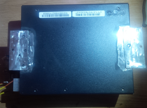
The initial idea was to sand two areas at the borders of the power supply and then using a soldering iron, to solder two fastening plates. The soldering iron method seemed to not work well with the aluminion due to limitations of the soldering iron. Instead, plain epoxy super-glue was used to attach the plates onto the power supply yielding a surprisingly powerful bond.
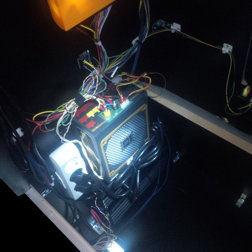
With all that in place, the power supply can be mounted inside the arcade cabinet and connected to the rest of the equipment.
Adding an Amplifier
The stock arcade cabinet benefits from two speakers, rated at about  that tend to output higher frequencies much louder without too much bass. The result is that sound effects, such as jumping, shooting or driving tends to blur out the volume of music in most games.
Furthermore, the stock speakers were connected to the headphones output of the LCD screen rather than the sound output of the Pandora box which tends to be counter-intuitive since headphone outputs are pre-amplified and sometimes even attenuated in order to fit small speakers that one would find on a headphone set.
Since arcade cabinets seem to mostly be powered by  and
and  , a perfect amplifier choice is a car amplifier since no power adjustment would be necessary and the amplifier can be powered directly from the power supply. Due to car enthusiasts, a wide range of car amplifiers are available and the offered power for the price makes such a choice effective. Similarly, car amplifiers are made to be minimal and to be fitted into cars such that their design tend to fill wall or bracketed mounts rather than having a home-theatre or bulky-looking geometry.
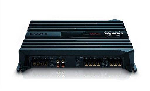
A Sony Xplod (XM-N1004) 4-Channel 1000 Watts amplifier was chosen mainly due to the power output, the low cost since the product has been discontinued and the fact that it has two separate channels for front and rear speakers, both of them benefiting from high and low-pass filters that would allow fine-tweaking the noticeable difference between the volume of sound effects and music that the cabinet seems to have trouble with:
Conveniently, the Sony Xplod has shoe terminals for speakers and for the power input - the latter being labeled REM, +12V and GND. With no further ado, the 12V and GND terminals can be connected to the power supply from the previous section and, as the manual indicates, in order for the amplifier to power up, the REM and +12V terminals are bridged using a copper wire. The REM terminal could possibly be connected to the +12V terminal via a switch in order to allow switching the amplifier on or off but it is not needed such that the amplifier will just turn on along with the rest of the arcade cabinet.
For the speakers, the stock speakers are connected to the "front" terminals of the amplifier and two additional speakers (preferrably subwoofers) are connected to the "back" terminals. Looking at the manual, the correct setup is to switch LPF on, and set filter to HP - although, LP could be attempted to solve the issue with the front speakers.
Adding an Arduino Controller
Whilst the IoT page on controlling an arcade cabinet with Alexa, uses a GPIO pin to turn the arcade on or off via two solid state relays, the solid state relays could only output  each such that the amplifier could definitely not be powered anymore. Nevertheless since the power supply has been swapped with a modified PC power supply that exposes a socket with
 PS_ON and GND leads, the SSRs are not needed anymore and the WeMoS board can simply make or break the connection to power up the power supply and thereby the entire arcade cabinet.
For brevity, the contents of the page describing how to control an arcade cabinet with Alexa will not be reiterated here. The only changes necessary to the original article is that the SSRs are to be removed and the leads have to be adapted to the newly added socket on the power supply. All the rest, including the node-red automation flow can remain just as it is.
With the current setup consisting in a modified power supply and the amplifier, the arcade will turn off properly using Alexa commands. However, the monitor is still powered from the plug extender such that the screen will not be completely turned off - this is slightly imprecise because the AOC monitor can sense the HDMI signal and will switch itself into power saving. Nevertheless, it would be nice to find a solution to be able to shut the screen off completely when the arcade is switched off via Alexa.
Powering the LCD from the Power Supply
The LCD screen is an AOC monitor powered via a kettle cable that plugs into the extender inside the cabinet. Given that the power supply switch will be controlled via an IoT micro-controller, it would be nice to be able to switch off the entire cabinet at the same time with the LCD monitor. Various solutions come to mind:
- modify the LCD monitor itself and bypass the AC-DC rectifier and power the LCD directly off the power supply meaning that the LCD would have to be disassembled,
- add a kettle socket to the power supply (like on older power supplies) but that would not work since the sockets are wired 1-to-1 and the monitor would still be permanently on
- add a power inverter from
 DC to
DC to  AC
AC
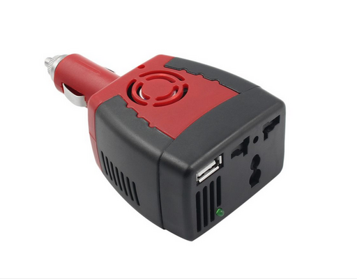
The last option was the chosen option and a very standard car power inverter was used - the power inverter plugs in a car to the lighter socket and offers a  socket and a
  USB socket.
Perhaps the main concern about the cheap power inverter is that the inverter will most likely produce a modified / square wave output on the  line which would not really be suitable for sensitive electronics. However, the LCD screen has an additional rectifier from
  to whatever DC voltage it is using such that the modified wave should not cause problems or interfere with the functionality of the LCD screen.
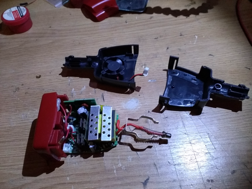
Since in this case there is no lighter socket nor is the USB socket useful, the power inverter will have to be modified by disassembling the case and removing the extra props that will not be used as well as cut to a more manageable size to be finally mounted on the arcade wooden wall.
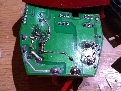
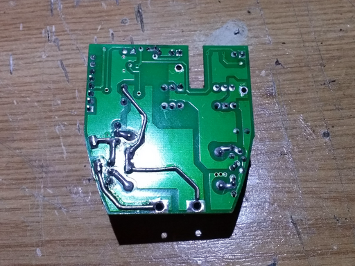
Just by disassembling the power inverter, one of the  leads disconnected from the terminal and came loose. Flipping the PCB over, a bunch of components seem to have been cold soldered:
and the device seems to have been assembled manually. This is to be expected from a cheap device but can be particularly dangerous in case of a short. Furthermore, the device is rated at  and the traces on the back of the PCB most likely will not be able to draw the corresponding amount of current.
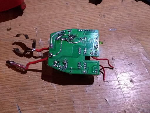
Moving on, the cabling of the device seems to be ill-suited for the power rating, the leads up to the  power socket (on the right) are extremely narrow to allow passing even
  .
.
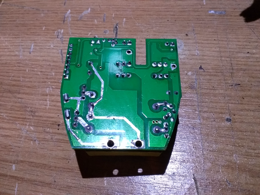
In conclusion, the device most likely should never be used as it is, except if it is post-processed by a technician that can restore it to some sensible condition. The PCB can be cleaned, resoldered properly and the traces exposed:
The traces seem to have been filled just with solder and it can be seen from the top upper left extremity of the trace that a very narrow contact is made to one of the PCB pins. Again, such a narrow contact could eventually singe the PCB over time and perhaps lead to an outright fire.
Using some copper wire, the traces can be reinforced yielding quite a reasonable product:
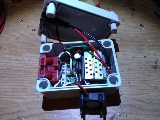
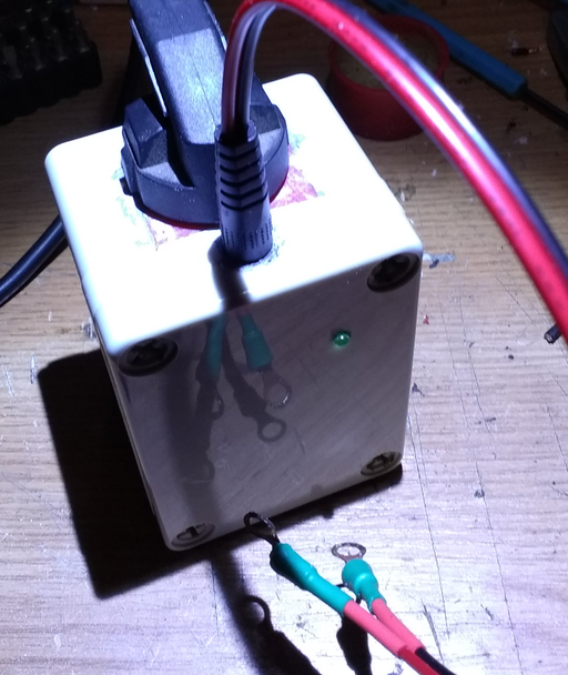
Parts of the case can be reused further, for instance, the socket plug instead of buying a new one. The components can all be enclosed in a box with some thicker wires connected to the terminals. A power jack can be added as well to seep  off the power supply.
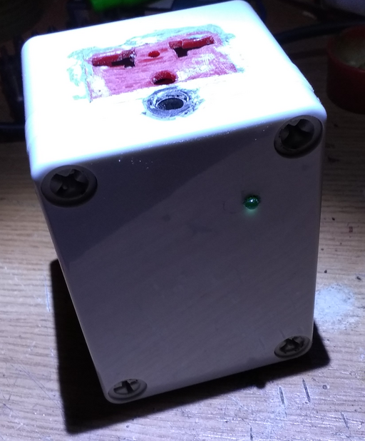
The power socket is cut out carefully using Dremel as well as an opening in the box and the socket is then fitted on the edge of the carved box. Some magic putty is used to coat all the openings and, after the putty hardens, the box is sanded down to give the box an uniform allure.
The box could also perhaps be repainted white in order to cover the red socket from the power inverter.
Note that the LED has been desoldered off the PCB, connected with wires and mounted inside a small hole on the box to make the visual feedback visible that the power inverter already had built-in.
The last step is to mount the power inverter box inside the cabinet alongst the rest of the components; connected to the power supply and the monitor plug is connected to the power inverter box.
Adding LEDs
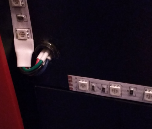
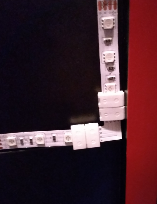
LEDs are added to the back of the cabinet and underneath. A remote-controlled RGB LED strip is used that is then cut and connected with right-angle connectors along the margins of the cabinet.
A hole is drilled straight through the back of the cabinet and some plastic tubing is inserted inside in order to prevent the wood from eroding over time (even if the wiring will not be removed all that often). Some JB weld two-part compound is used to both hold the plastic tubing in place and to seal any exposed wood resulting from the drilling.
Angle connectors are perhaps the best choice compared to bending the LED strips in order to obtain right angles. The LED strips are cut at the indicated points on the strip, then slid into the right angle connectors and fastened down. The strips are supplied with some adhesive on the back that seems to be sufficient to hold the LEDs in place.
One remaining problem is the infrared sensor that would have to be exposed but given that the LED color will not change much, the remote can rest inside the cabinet.
Raspberry Pi and Jamma
Hooking up a PC or a Raspberry Pi requires either an USB encoder that can map the joystick and the buttons to USB compatible signals, a JPAC that connects a PC to a Jamma cabinet or, for the Raspberry Pi, a Pi2Jamma device that allows a Raspberry Pi to be connected to a Jamma cabinet by harnessing the GPIO pins.
A Pi2Jamma and Raspbery Pi 4 device have been chosen for the project in order to maintain the classic Jamma interfacing - other options would have included getting an USB encoder in order to translate the joystick and button controls to USB and bypass the Jamma altogether.
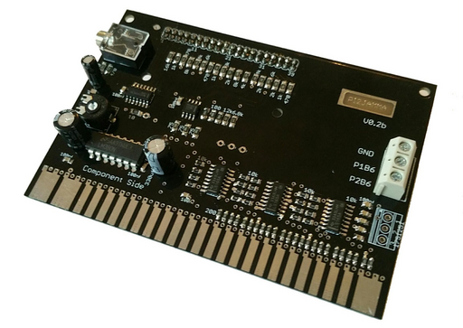
The Pi2Jamma board from strike devices is a device that allows a Raspberry Pi to be connected to the Jamma arcade cabinet.
Usually, the Pi2Jamma board is used by older arcade machines that have a  monitor such that the HDMI signal from the Raspberry Pi has to be converted. In this case, the Pi2Jamma is used just for connecting the Raspberry Pi to the controls.
When converting from a 6 button Pandora Box to a Raspberry Pi with a Pi2Jamma interface, the 6th button wires will have to be detached and connected to the Pi2Jamma board since the Pi2Jamma will only translate 5 buttons on the Jamma connector.
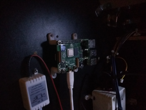
The Raspberry Pi 4 is mounted inside the cabinet instead of the Pandora box,
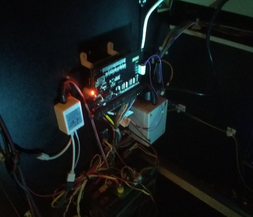
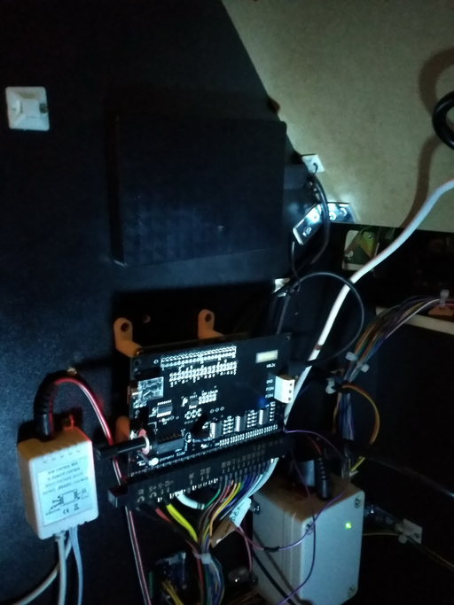
and the Pi2Jamma is connected to the GPIO pins socket.
The Pi2Jamma manufacturer at arcadeforge.de does provide some software solutions but regrettably none of them are compatible with the Raspberry Pi 4 at the current time of writing. Even so, the software solutions provided by the Pi2Jamma manufacturer are lacky in terms of features and perhaps really geared towards classic arcade machines - especially since Pi2Jamma is designed specifically with the goal of generating a  output signal instead of using the HDMI port on the Raspberry Pi directly.
RetroPie is a popular solution however RetroPie has not yet been updated to include support for the Raspberry Pi 4. Furthermore, attempting to compile RetroPie on Linux yields in numerous compilation errors. Most of the errors stem from the Raspberry Pi's OpenGL support as well as having to pick between a fake KMS framebuffer or running Xorg. Some third-party RetroPie distributions exist based on Debian but the setup boots into the GNOME desktop and only then starts emulationstation, the RetroPie frontend.
An alternative that seems to work out of the box is Lakka which, unfortunately, has its own pitfalls. Lakka is based on LibreELEC and is designed to be tamperproof, even with root access - this would be good in other circumstances but since Pi2Jamma is used, some changes to the Linux filesystem would have been desirable and Lakka does not offer read-write access to the underlying filesystem.
In any case, Pi2Jamma uses pikeyd to translate the joystick and the button controls. The pikeyd source is available on github but perhaps the best choice is to install the pinHP software package provided by arcadeforge.de and then extract pikeyd. For convenience, the relevant files are attached here:
pikeyd maps arcade cabinet controls such as the joystick movements or button presses to standard keyboard keys. Emulators can then be configured to map the keyboard key presses generated by pikeyd to relevant game actions - very trivial in terms of functionality.
To install pikeyd, connect to a wireless network from Lakka and then activate the SSH service in Lakka by navigating the menu to Settings -> Services. SSH into Lakka using the default root user with password root and create a subdirectory, ie: pikeyd. Unpack the provided pikeyd.zip file inside the pikeyd directory and copy pikeyd165_default.conf to ~/.pikeyd165.conf. Then, create a file at ~/.config/autostart.sh with the following contents:
#!/usr/bin/sh

# Kill previous instance of pikeyd
/storage/pikeyd -k
# Start pikeyd as a daemon
/storage/pikeyd -d
and make ~/.config/autostart.sh executable by issuing chmod +x ~/.config/autostart.sh.
With this setup in place, whenever the arcade cabinet is restarted, pikeyd will be started on boot in order to map the arcade controls to arcade actions.
One common problem that you will see in many arcade tutorials and you will most likely be told if asking is that when switching from a Pandora Box arcade machine to a Raspberry Pi / RetroPi machine, additional buttons have to be added such as "Select" and "Start". However, instead of drilling more holes into the arcade cabinet, pikeyd is able to map combinations of one or more buttons to custom buttons. For instance, opening up ~/.pikeyd165.conf reveals the following configuration at the bottom of the file:
#special keys! bits pressed simultaniousley result in specified Key
#maximum bits == 4

#Example:
# player1 start / p1b2 / p1down
KEY_ESC        17 11 19
# player1 start / p1b3 / p1down
KEY_F1         17 0 19
where the first line starting KEY_ESC will generate an escape ESC button press whenever the start, sixth button and joystick are held down.
Lakka tends to use two additional keys to operate the menus and other features: the escape key ESC and the return key ENTER. These can be both mapped to, say, holding the start button and moving the joystick up and holding the start button and moving the joystick down via the following configuration:
#Example:
# player1 start / p1down
KEY_ESC        17 19
# player1 start / p1down
KEY_ENTER      17 18
With that configuration in place, the combos can be mapped to "Start" and "Select" by navigating the Lakka menu to Settings -> Input. In effect, Lakka does not care whether you have a "real" controller or not, Lakka most likely listens to standard Linux low-level keyboard events and maps whatever button Linux can sense to an action such as "Left", "Up", "Button A", etc.
Similarly, some modern games use more buttons on standard controllers that are rarely needed in anything from classic arcade but up to most recent consoles (ie: the PlayStation) - buttons that can be mapped using pikeyd to multiple button presses instead of adding yet more buttons to the arcade cabinet that would only end up being used on a very small fraction of games.
As a failsafe, a compact wireless keyboard and mouse combo can be attached to the Raspberry Pi to be able to control the arcade machine in an emergency.
As a further development, perhaps a jamma extender could be used to hook up both the Raspberry Pi / Pi2Jamma and the Pandora Box simultaneously to the arcade machine.
Fixing Power Issues with Raspberry Pi 4 an Pi2Jamma
In this configuration it sometimes happens that the Raspberry Pi 4 complains in the logs about undervoltage:
Under-voltage detected! (0x00050005)
Voltage normalised (0x00000000)
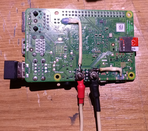
With two wires attached, more amperes can be supplied to the Raspberry Pi 4 directly from the PC power supply.
The + terminal (red) connects to TP2 on the PCB and the negative - terminal (black) connects to the ground on the mini USB3 connector in order to benefit from the protection that the Raspberry Pi 4 has built-in.
Adding Storage to the Raspberry Pi
Since a Raspberry Pi 4 has been used, some USB3.0 storage can be attached to the Raspberry in order to spare the micro SD a few read/write cycles as well as benefiting from more space and faster access times.
A cheap and solid option is to use an external hard-drive with USB3.0 such as the Seagate 1TB 2.5" portable storage.
In fact, the Seagate 1TB 2.5" portable storage enclosure can be opened and the hard-drive can be replaced with an SSD such as a cheap ADATA at 128GiB. As of 2018 the largest and most complete ROM collections span about 40 to 50GiB in size such that a 128GiB drive seems more than enough.
The enclosure is mounted on top of the Pi2Jamma and the Raspberry Pi:
Integrating a Trackball
Even if there is no space on the arcade control board to fit a trackball, it might be possible to add a trackball device to the top frame (the one right above the screen). Originally, the thought would have been to include a flick-board and then use gestures as a control measure, in particular since it would have been much cooler. Nevertheless, respecting the era of the arcade, a manual trackball would be more fitting of the style.
Foreseeably, some axis direction swaps might be necessary since the trackall device would be fastened upside down.
Furthermore, the trackballs available are connected via PS/2 whereas the redesigned arcade machine with the Raspberry Pi only benefits from USB ports. A small gamble away, it was thought worth the trouble to attempt and couple the trackball device to a PS/2 to USB converter and attempt to fit the trackball anyway.
One limitation of the placement of the trackball would be that the arm of the player would hide the screen. Nevertheless, since the arcade is now running on retroarch, some interesting features could be achieved. For example, the left and right axis directions could be mapped to the rewind (Settings->Input->Rewind), respectively fast-forward hotkey (Settings->Input->Fast-Forward (Hold)) control options, whilst pressing the trackball button would activate the slow motion feature (Settings->Input->Slow-Motion (Hold)). This would represent a time-shift trackball, where the backward motion would activate a rewind of the game and a forward motion would activate a fast forward and the trackball button could activate the slow motion for clarity.
In effect, this would represent some sort of ubiquitous game cheat based on the gameboy oscillator mod, yet stylish enough to be integrated into an arcade machine. Some adjustments would have to be made, for example, Settings->Frame Throttle->Rewind->Rewind Buffer Size (MB), could be scaled to the overall available memory on the machine powering the arcade, given that playable emulations do not use that much RAM anyway.
Replacing the Joystick and Buttons with Illuminated Counterparts
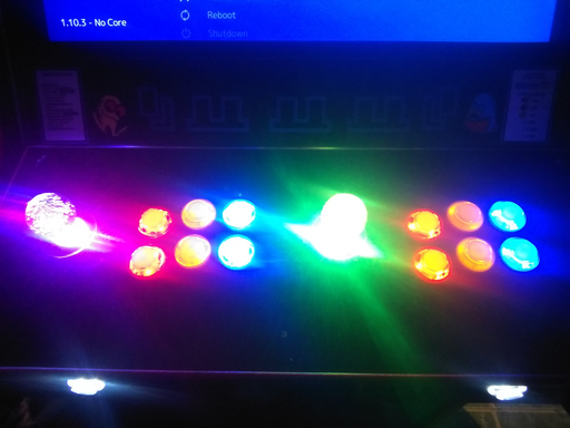
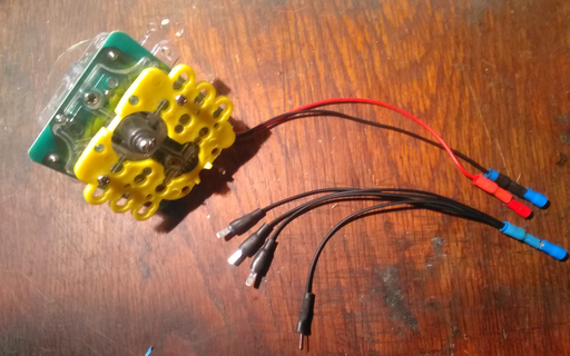
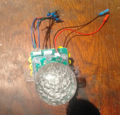
Replacement buttons and joysticks are easily found and for this project it was considered that adding illuminated counterparts would add a good look to the arcade machine. Illuminated buttons and joysticks are rated at specific voltages that should be respected in order to not burn the circuits. Irrespective of the switches, the illuminated buttons and joysticks have two additional leads that light them up by powering them conventionally via the Jamma harness. For this arcade, it was decided to not mess with the Jamma harness any further and to draw power directly from the PC ATX power supply.
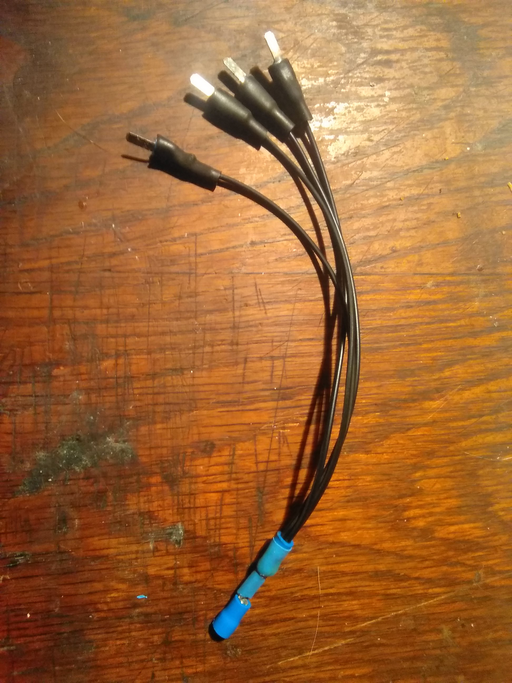
Perhaps the most difficult part is to create harnesses in order to draw power and then distribute it across all the buttons and the joysticks. Trivially, the chosen circuit is a parallel circuit where all the positive and ground lines are connected together via a long cable with the ends sealed off with cold terminal pins in order to connect them to the pins of the buttons and the joysticks.  of LED ribbon lighting cable seemed to be most suitable since LED lighting cables commonly have four separate wires that can be stripped separately in order to create positive and negative leads.
To add to the difficulty, in this particular case, the joysticks were rated at  and the buttons at
  such that two separate leads were required to connect the buttons together and the joysticks together separately. Furthermore, the joysticks had a pin-array connector that required a separate cable harness to be created in order to adapt the existing circuitry.
The rest just involved connecting the pins together on the joystick and reusing the existing circuitry.
The pins on the joystick are luckily labeled and the cables have been in this case soldered directly to the pins of the joystick corresponding to the various directions of the joystick.
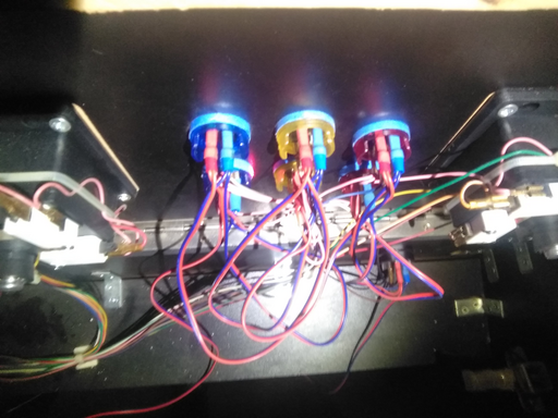
On the inside the connections can get a little tricky since now there are two sets of cables running in parallel: the original harness that connects the microswitches together and a separate harness that brings power in order to light the buttons and the joysticks.
The result is still very pretty, and goes exceptionally well with darker environments.
ROMs
It appears that both RetroArch / Lakka and RetroPie use multiple emulators in an attempt to increase game coverage. Both emulators are capable of automatically scanning ROM collections and adding the box art to each game. English speakers may tend to wipe out the ROMs meant for other languages and others may have regional preferences but the catch is that if Netplay is to be used, then the exact same ROM (CRC et al.) is required on both arcade machines. That is, even though an emulator may be able to run a customized ROM or a ROM meant for a certain region, it is uncertain whether the other person joining the Netplay session may have the exact same ROM (up to the last indivisible bit of data).
There are two well-known ROM collections for emulators other than MAME:
- EverDrive
- NoIntro
EverDrive is a collection made with everdrive hardware devices in mind - a modern solution to carrying cartridges where an EverDrive cartridge is used with an SD card to hold all ROMs. Unfortunately, the EverDrive collection contains a single ROM from all sets and mainly focuses on the USA ROMs.
NoIntro is a different collection that represents an effort to dump every single original cartridge in mind including regional ROMs but excluding hacks or modified ROMs. In that sense, the NoIntro collection is most likely a superset of the EverDrive collection and should be a safe bet if Netplay is required.
MAME
RetroPie and RetroArch / Lakka best emulate ROMs for the following versions of MAME:
- ROMs for MAME version
0.37b5, - ROMs for FBA
v0.2.97.39, - ROMs for MAME version 2003 Plus
These and only these sets can be considered to be fully Plug and Play - all other ROMs may run, or may run poorly or may just not run at all.
RetroPie and RetroArch / Lakka do include emulators for MAME versions above 2003 Plus, such as 2006, 2010, 2016 but the emulators are not yet finished let alone polished such that running under the Raspberry Pi will most likely not work very well.
Furthermore, using any different collection other than the sets mentioned above (while also paying attention to what other users say about RetroArch compatibility) seems to throw RetroArch off completely such that the games may not even show in the list after a full scan.
Nevertheless, the good news is that the working versions mentioned above would cover most, if not all, of the retro experience. Even having Netplay in mind, it will never happen that you will find someone running a lobby for a 2016 MAME game.
The CHD Scanning Issue
The 2003+ collection has some directories that contain CHD files. CHD files are meant to be hard-drive dumps but RetroArch, at the time of writing, will stall on scanning CHD files. To avoid this problem, temporarily move the directories as they are to a different location, scan for roms and when the scanning is complete, copy the directories back in the same directory with the ROMs.
Organizing ROMs
ROM collections have naming conventions that are well-defined, for instance, the TOSEC naming convention covers everything from release date and describe up to ancient retro-viruses that ROMs may be infected with.
Some users prefer to rename the ROMs to something more human-friendly, but a good decision is to leave the ROM collection unchanged, including the folder structure since it provides a common reference for updates, replacing or recovering ROMs in case of failure.
MAME ROM collections can also be organized and split up into various folders depending on their versions.
For the contact, copyright, license, warranty and privacy terms for the usage of this website please see the contact, license, privacy, copyright.
