Table of Contents
Status LED Flashing Red on Transmit
Even though not specified within the documentation, a flashing LED on the left-hand side of the Yaesu FT-891 could mean that transmission on the selected frequency is not allowed. This is particularly challenging to figure out, in particular because the Yaesu FT-891 is configured out of the box to not allow transmission on the 11m citizen band (CB), which should not be the case due to CB being perhaps the most public amateur band of all bands that does not even require a license.
Enabling MARS
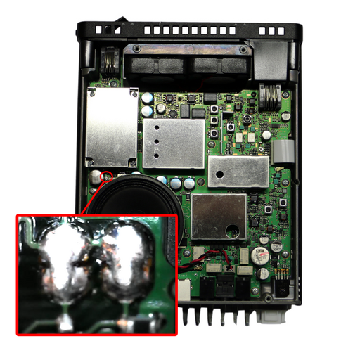
Enabling MARS mode involves removing the top cover and soldering two sets of vertical pads parallel to each other together. This will allow transmission out of the preconfigured allowed bands, in particular the modification will allow transmission on the 11m CB band.
Creating a DATA Cable
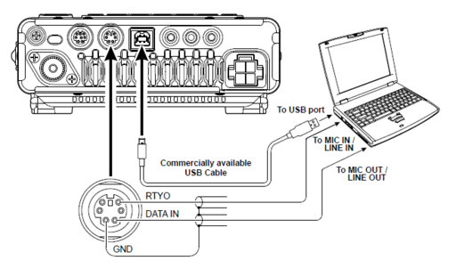
Page 64 mentions how to connect the Yaesu FT-891 to a computer in order to be able to use the ham radio DATA mode.
Aside from USB, the line-in and line-out seem to be straight-through connections:
| Yaesu FT-891 | PC |
|---|---|
RTYO | LINE IN |
DATA IN | LINE OUT |
GND | GND (common to LINE IN and LINE OUT) |
The data port connector is a DIN connector (compatible with a PS/2) jack such that creating the circuit is fairly easy.
The only problem is that even if the PS/2 cable is salvaged from a keyboard or mouse, the connector must still be cut open due to some of the pins not corresponding to PS/2 cables.
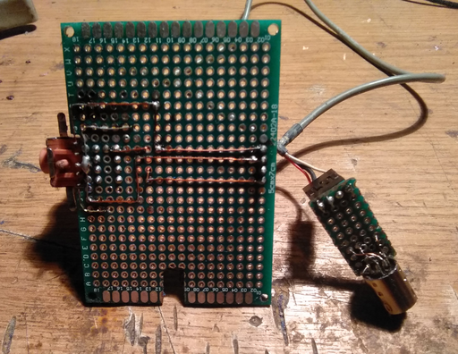
Both lines, the ones stemming from the Yaesu RTYO and DATA IN are connected to the uppermost part of the 3.5mm audio jack in order to correspond to a mono connection. The 3.5mm jacks are then connected directly to a soundcard, following the schematic. In doing so, the LINE IN line effectively becomes a headphone port and the radio can be listened to using the soundcard. One of the drawbacks is that once the lines are connected to the Yaesu, and if the external speaker jack is disconnected, then the Yaesu speaker becomes active. One easy hack to mute the Yaesu speaker is to just insert a floating 3.5mm jack into the external speaker port.
The large PCB could be trimmed down further but it allows enough room for an amplifier, perhaps to amplify both the line-in and line-out signals bearing in mind that the radio DATA mode depends heavily on the quality of the sound output of the radio.
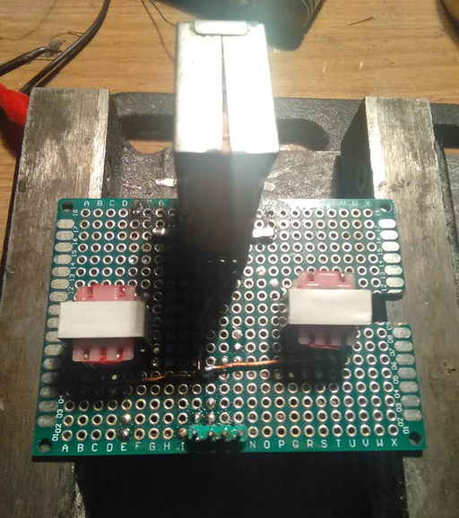
In order to isolate the signals, some 1:1 transformers can be added to the circuit, in line with the microphone and line out jacks.
The modification has the following schematic:
 MIC +------------+ +--------------+ MIC
                  3 E
                  3 E 1:1
 GND +------+-----+ +------+-------+ GND
            |              |
            |              |
            +-----+ +------+
                  3 E
                  3 E 1:1
LINE +------------+ +--------------+ LINE
where the ground pins of both jacks are connected together and the MIC and LINE connected to the other pins of the 1:1 transformers.
For a more advanced device based on the same build, please see the VOX circuit for HAM radio.
WSJT-X Data/Pkt Mode and Yaesu FT-891
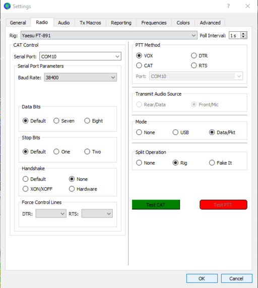
While WSJT-X recommends the Data/Pkt mode when available:
the tooltip over the Data/Pkt radio button reading "If this is available then it is usually the correct mode for this program."
It might seem that when switching to the Data/Pkt mode, the FT-891 does not seem to decode anything compared to using the standard USB mode.
One problem might be that the FT-891 is configured to use LSB data mode instead of USB data mode that can be observed from the icon under VFO-A reading D-L instead of the correct D-U.
The solution is to go to the menu settings, locate DATA BFO (item 08-12) and set it to USB instead of LSB.
Note that when using USB mode, the FT-891 also additionally couples the handheld microphone such that you will be transmitting noise as well. Obviously, one solution is to just unplug the FT-891 handheld microphone when using WSJT-X.
Using both the ATAS-120A and the FC-50 Tuner with the Yaesu FT-891
Even though the manual states that the ATAS-120A cannot be used with the FC-50 tuner, it is still possible to do so unofficially. One possible advantage would be that whilst the ATAS-120A would be responsible for adjusting to a chosen band, the FC-50 tuner can then be used after that in order to reduce the SWR to a minimum. In short, just power off the radio when switching between the ATAS-120A tuner and the FC-50 (EXTERNAL menu item) in order to ensure that they do not conflict.
Ultimately, it has been observed that the conflict between the Yaesu FC-50 antenna tuner and the Yaesu ATAS-120A antenna hinges on whatever is connected to the Yaesu antenna port. In other words, the mini-DIN connection between the FT-891 and the FC-50 does not affect the tuning if the ATAS-120A were to be connected directly to the FT-891 antenna port. That being said, a trivial solution is to use an antenna splitter, for instance, a remotely controlled mechanized antenna switch, and then switch between the FC-50 tuner and the ATAS-120A when tuning for a frequency. The operation would take place along the following lines:
- commute the splitter to the ATAS-120A and set the tuner to
ATASin the FC-891 options menu, - tune using the ATAS-120 antenna,
- commute the splitter to the FC-50 and set the tuner option to
EXTERNALin the FC-891 options menu, - tune using the FC-50
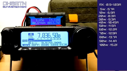
Power Consumption
For the contact, copyright, license, warranty and privacy terms for the usage of this website please see the contact, license, privacy, copyright.
