Table of Contents
About
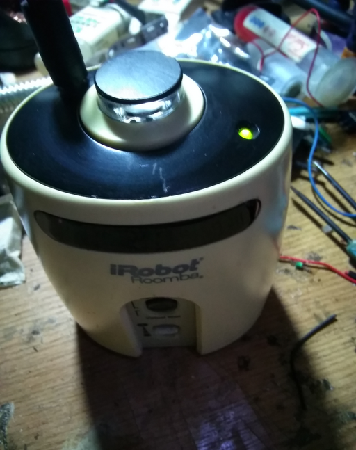
One of the problems with the Roomba lighthouse is that it is powered by two "rare" LR14 batteries but has no way of being powered via the mains. The only reason for a device to be powered by batteries is to ensure that the device can be conveniently moved to a different location. However the lighthouse is semi-mobile and once the positions around the house are established, the lighthouse is not bound to be moved between locations all that much. The following modification of the lighthouse adds a power jack such that the lighthouse can be powered externally without requiring batteries.
Requirements
The modification is pretty straightforward and more of a mechanical modification that requires little knowledge in electronics and requires more of a hobbyist experience.
- power jack,
- step down module,
- dupont wires
As well as a dremel and soldering equipment.
Finding the Proper Position
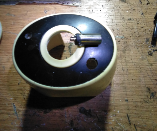
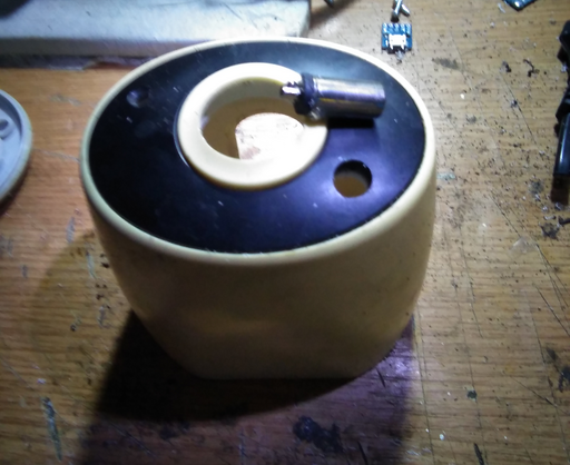
The lighthouse construction is compact for the electronics it carries and is rather tight on the inside such that no position seems to be suitable. Naturally, the jack should be placed somewhere out of the way that would not impede the functionality of the lighthouse. On the back of the lighthouse there is little space between the exterior of the lighthouse and the cylinder containing the batteries. A position at the top of the lighthouse has been picked since it does not increase the surface occupied by the lighthouse and the jack would be easily removed. The difficult part is drilling a precise hole to fit the jack inside with the extra requirement that the bottom of the jack does not short the PCB immediately underneath the lighthouse cover.
The hole must be drilled through the lighthouse chassis and through the black top cover.
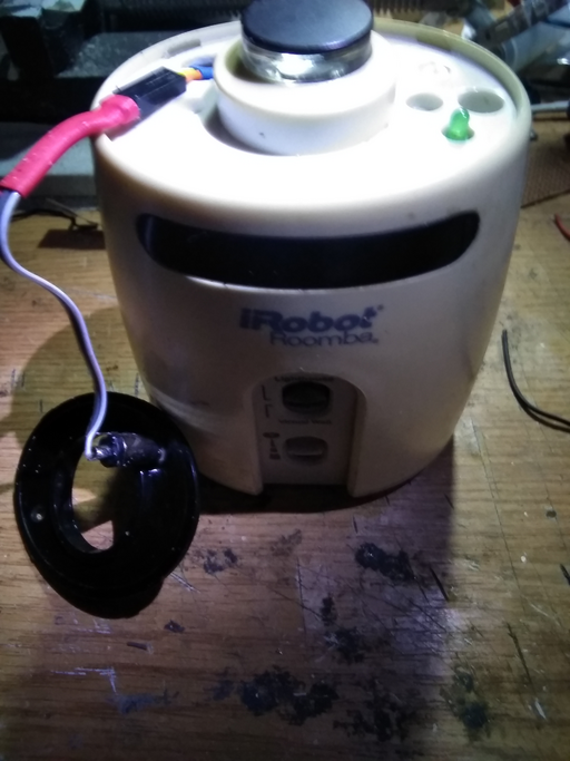
Dupont wires can be used to connect the jack to the circuitry inside the lighthouse. The Dupont connector fits well inside the hole inside the chassis. The jack itself can be glued to the upper black lid using epoxy glue and left to dry off.
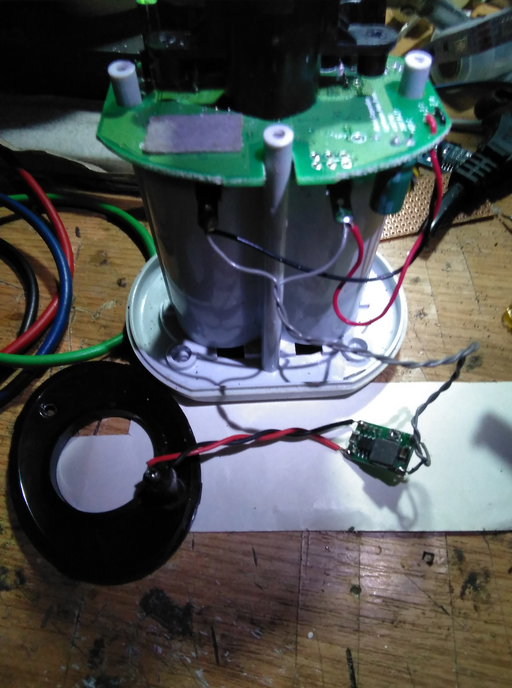
The circuitry is fit on the inside of the lighthouse by connecting the step-down module to the battery contacts directly. The circuitry is trivial: the input of the module is connected to the power jack, expecting a range of  to
to  of current to be fed to the module whilst the output of the module is connected to the battery contacts. Using a voltemeter, the step-down module is adjusted to fit the 3V required to drive the lighthouse (two LR14 batteries, each rated at
  ). Although this works properly, the batteries should not be inside the lighthouse when the external power jack is connected.
Putting it all together and connecting the power jack, the lighthouse will display a few flashes of the LED showing that the lighthouse is functioning properly.
Further Developments
As per the previous section, the batteries should not be inside the lighthouse when the lighthouse will be powered by the external power jack since the module used for this modification is not a battery charger. This design was preferred since the lighthouse in this case is very static and will not be moved around a lot - even if the lighthouse will be moved, it will be connected again to the nearest mains. Even so, for some extra sophistication, the step down module can be replaced by a battery charger (NiCd, LiPo, depending on the batteries to be fitted inside the lighthouse). Such chargers have the extra ability to stabilize the current and provide a proper recharge of the batteries with the extra benefit of decoupling the charge once the batteries are full in order to avoid overcharging the batteries.
