Table of Contents
About
Wall-mounted domestic air conditioners are an affordable, albeit lamentable, solution for cooling and heating as an alternative to the more expensive climatized homes. Wall-mounted air conditioners are wide-spread and come in a very large variety with very similar features.
The air conditioning unit consists of two parts: one part is placed on the outside of the building and the other is placed inside a room with a connector going through the wall.
The device inside the room is plugged into the mains and then controlled typically using an infrared remote control.
These wall mounted devices have very typical operating functions to be found for a wide range of producers. Here is a list of what such a device can do:
mode- the mode button can switch between cooling, blowing air, heating, etc...switch- these devices are toggled on and off by pressing a single button,fan- the air conditioning devices support between one and four fan speeds and the fan button toggles between fan speeds,swing- the bottom part of the device unfolds a flap allowing air to be blown through the aperture and the swing function makes the wall mounted device swing the flap,- adjusting the temperature - all devices support setting the temperature, whether the device is in the cooling or heating mode; in some ways, this adjustment is prophylactic because the device does not use a sensor to check the ambient temperature such that this setting just specifies the temperature that the device is set to attain.
One incidental and probably unintended feature of budget wall-mounted air conditioning devices is that the remote control from one brand of devices will work with a different brand of air conditioning of the same genre. One can effectively use a remote from a different producer to control a wide range of air conditioning devices made by other producers.
Project Description
In order to control the air conditioning device programatically, perhaps, say, through Alexa, the project will modify an universal air conditioning remote control in order to create a controller device suitable for any air conditioning device.
Requirements
This project is split up into two parts: software and hardware so there are two sets of requirements for completion.
Hardware
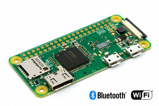
- Raspberry Pi - the Raspberry Pi benefits from a connector with GPIO pins that can be used to press and depress a button on a remote control. Any Raspberry Pi model is fine since all Raspberry Pi devices have similar connectors. This article has used a small Raspberry Pi W with wireless connection that will be able to reconnect to the wireless network every time the power goes out such that the device will be robust enough to withstand power outages. Furthermore, the Raspberry Pi packs just the right amount of GPIO pins in order to control all of the buttons of a remote control. Contrary to what the official Raspberry Pi creators say, the Raspberry Pi is not too cheap: devices are advertised using words such as "the USD5 computer" but in reality they go for USD20 and bare-bones from retailers. Nevertheless, they are still under the price of a second-hand computer and given the lack of features, also power-efficient.
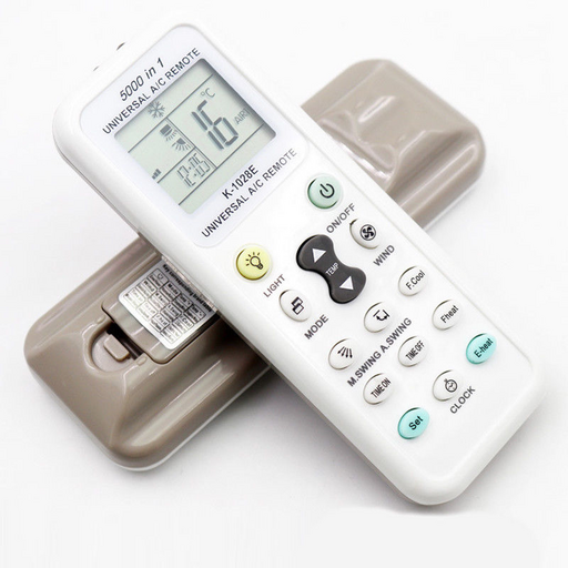
- An universal air conditioning remote control - due to the low complexity of remotes and wall-mounted air conditioning devices, there are many producers, particularly from China, that offer remote controls advertised as able to control "over 5000 devices". In essence, these universal air conditioning remotes have a
searchbutton that will sweep known frequency ranges to find just the right frequency range for controlling the wall-mounted device. The price range for such a remote is between USD2 and USD4 and they can be found allover the place, especially on EBay from Chinese sellers - you won't cry if the modifications fail.
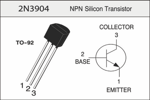
2N3904NPNtransistors (as many as buttons on the remote control). The2N3904is a general purposeNPNtransistor for low voltage and amperage that are going to be used as a switch to simulate a button press.2N3904is a very (intentionally) cheap multi-purpose transistor following the "cheap by the dozen" rule: 1002N3904cost around USD1 so feel free to go crazy with the supplies.
 resistors - the resistors will be used as a pull down to regulate the amount of voltage between the collector and emitter of the transistor. These are also "cheap by the dozen" and can be found in any electronics shop.
- female-to-female Dupont cables - used for connecting the Raspberry GPIO pins to the modified remote Dupont pins.
- IDC male connector - these are breakable using some pliers to obtain individual pins that can be fixed onto the remote control.
- [Optional depending on Raspberry Pi]
 to
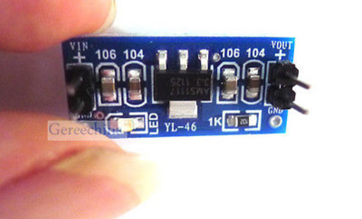
to  stepdown - all remotes are fed by 2 AAA batteries which are rated at
  each resulting in
  . Unfortunately, the RaspberryPi W
  output is rated at about
  which is insufficient to power the remote directly. Consequently, the
  output from the Raspberry Pi will be used instead (capable of providing between
  and
and  ), coupled with a stepdown circuit to provide enough current to the remote. As per the pattern: "cheap by the dozen", USD1 each and they contain an integrated circuit ensuring the output.
What is not included in this list are the usual apparatus used for soldering and, perhaps, a multimeter to check that the circuits work correctly. Note that common-sense tools such as tweezers, pliers, some alcohol to clean the circuit board should also be available.
An essential tool would be a small drilling machine since the components will be attached directly onto the remote control and holes will have to be drilled through the PCB. Wholeheartedly recommended is a Dremel device with carbide head drills with head diameters between  to
to  :
:
Whilst the Dremel device is not cheap - it is an indispensable tool and while you are at it, you might just want to automate the Dremel as well using a Sonoff IoT device.
Software
- Raspbian for the Raspberry Pi - other Linux variants are also acceptable; this article uses Raspbian out of convenience to be in-line with the rest of the documentation.
- Mosquitto Client - installed in Raspbian on the Raspberry Pi by issuing
aptitude install mosquitto_clients. The software created by Wizardry and Steamworks will subscribe to a topic on an MQTT broker and then press buttons on the remote depending on published messages. In doing so, OpenHAB2 can be used to bridge Alexa with the controller for voice control. - Node.JS and NPM - installed in Raspbian by issuing
aptitude install nodejs npm. These are needed to run the software provided by Wizardry and Steamworks. - Subversion - to check out the sources offered by Wizardry and Steamworks (
aptitude install subversion). - [Optional] OpenHAB2 - a general control panel and control center additionally providing a bridge to Amazon Alexa.
- [Optional] Amazon Alexa - optional, for voice commands.
Overview Diagram
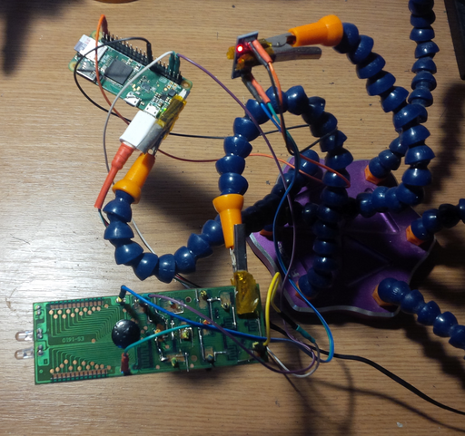
Here is a general overview diagram of the project illustrating how the various components interact.
Modifying the Almighty Remote
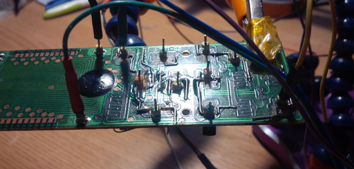
The almighty remote (unfortunately) has graphite-activated contacts for buttons such that the only way of attaching components is to use a scalpel and gently scrape the board to reveal the copper contacts to which components can be attached. Additionally, the carbon contacts on the remote are scraped off using either a Dremel with a fine small polishing wheel or with a scalpel - this is done to prevent the carbon contacts to interfere with the transistor and resistor leads when fitting them onto the remote control PCB. It will not look pretty but it will be safe.
Next, the board is drilled through to create three holes to fit the transistor and resistor. When drilling, it is important to mind the traces - the best place to drill is on top of the scraped off carbon contacts. The remote PCB can be placed against a bright light source to check that the drill locations will not sever any leads.
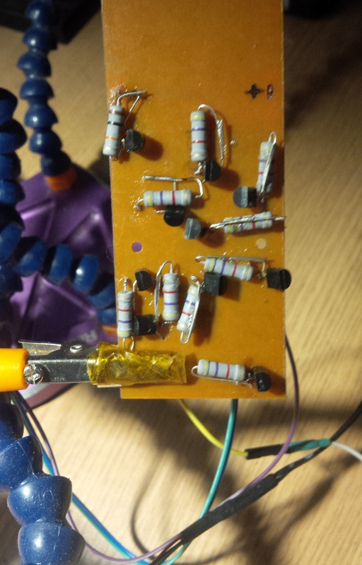
The collector and emitter is soldered to the contacts of a button on the remote whilst the base is soldered to one side of the  resistor. The other side of the
  is then connected to a dupont-type pin that is fixed on the board. The design is ideal for testing because one can connect a female-to-female dupont cable between the remote and the GPIO pins on the Raspberry Pi.
In some instances, the graphite traces have to be remade using short metal stubs, such as the ones collected from trimming the transistor or resistor leads. You can observe that the remote has several leads on top that had to be recreated in order to preserve the circuit wiring.
Overall, the modification of the remote is a meticulous business so a lot of patience is necessary to get every button right. One last thing to observe is that not all buttons have been modified - this is because some of the buttons are remote-centric functions such as a "timer" or setting the remote's date and time which are not necessary or irrelevant and can be handled by the software instead of leaving that up to the remote.
Circuit Design
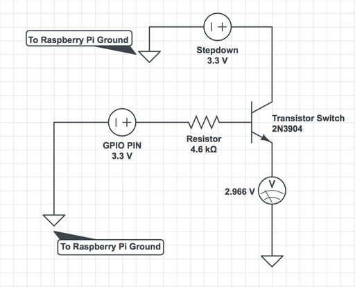
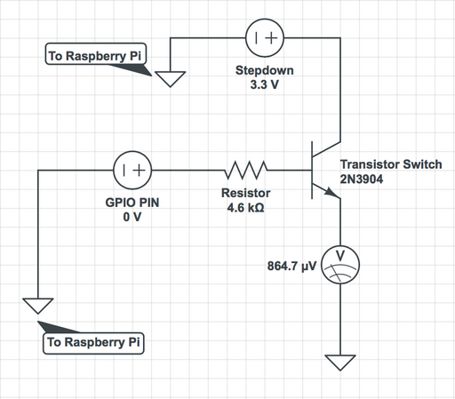
The circuit will use the 2N3904 BJT transistor as a switch to allow a total of  to pass between the contacts of a button on the almighty remote:
When the GPIO pin of the Raspberry Pi is set to logical high, 3.3V will be fed to the base of the 2N3904 transistor which will  to pass between the collector and emitter.
Conversely, when the GPIO pin of the Raspberry Pi is set to logical low, the voltage flowing through the button contacts will be  which is insufficient for the button to trigger the command.
Given the circuit, the software on the Raspberry Pi will have to set the GPIO pin to high, pause for a time period and then set back the GPIO pin to low in order to programatically simulate a button press.
Note that the voltage supplied by the stepdown circuit is  and it has been established that the remote is powered by
  instead of
  - the
- the  difference does not matter all that much and it seems to be within the tolerance levels of the remote and the current flowing through the switch will still be within a decimal place of the
  required to press the button.
Checking GPIO PIN Functionality
Each button can be tested by using a dupont female-to-female wire leading from a Raspberry Pi pin and onto the remote dupont pin. For testing, Raspbian has a tool named raspi-gpio that can be installed by issuing:
aptitude install raspi-gpio
Suppose that the modified On/Off button Dupont pin on the remote leads to the Raspberry Pi GPIO pin 16. Then, the first thing to do is set the GPIO pin 16 on the Raspberry Pi to be an output pin:
raspi-gpio set 16 do
where:
16is the GPIO pin number,doinstructsraspi-gpioto set pin16as an output pin
The command does nothing except declare to the Raspberry Pi that the GPIO pin will be used to output data instead of being an input.
Next, the following chained command:
raspi-gpio set 16 dl && raspi-gpio set 16 dh && sleep 1 && raspi-gpio set 16 dl
will preform, in order:
- set the GPIO pin
16to logiclow, - set the GPIO pin
16to logichigh, - pause for 1 second,
- set the GPIO pin
16to logiclow
which is an approximation of a button press on the modified remote control.
This procedure can be used for testing because it is handy and quick but a more permanent solution is provided for production.
Almighty Remote
The almighty remote recommended in the requirements section can determine the correct infrared frequency for the air conditioner via two methods:
- using the original remote and programming the almighty remote,
- holding down the
setbutton until the wall-mounted air conditioner beeps (searching)
Assuming that the Raspberry GPIO pin 16 is conected to the set button on the almighty remote, the second method involves setting the GPIO pin 16 to high:
raspi-gpio set 16 dh
and waiting for the the wall-mounted air conditioner to beep, immediately issuing:
raspi-gpio set 16 dl
afterward to set the GPIO pin to low.
The remote will now have found the correct frequency and the other GPIO pins can be connected to the various modified Dupont pins on the almighty remote to check that the buttons are working correctly.
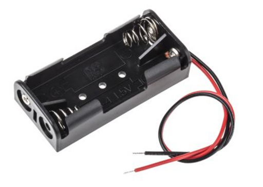
Unfortunately, the almighty remote needs to be permanently powered in order to retain the found frequency. One solution is to find a two-slot AAA battery holder and couple the leads to the almighty remote power pins. This will ensure that after a power outage, the correct frequency will still be retained since the remote will have been powered by the batteries.
When all the buttons function correctly, a more permanent solution can be deployed.
Production Software Solution
Wizardry and Steamworks offers a small controller software suite named "Cool-IoT", licensed under GPLv2, that is capable of toggling the buttons on and off by subscribing to an MQTT server. To install the software, change directory to /usr/src/ and checkout the latest source:
svn co http://svn.grimore.org/cool-iot/trunk cool-iot
Next, pivot inside the cool-iot folder and install the required Node.Js modules by issuing:
npm install
Edit the configuration file config.yml and set:
- the address of the MQTT server,
- the topic to subscribe to
and make sure to map the various remote control functionality to the corresponding pins:
GPIO:
  search: 16
  switch: 20
  up: -1
  down: -1
  cooling: -1
  heating: -1
  mode: -1
  swing: -1
  swipe: -1
  fan: -1
For instance, in the default setup the GPIO pin 16 is mapped to the set button of the almighty remote that sweeps to discover the correct infrared frequency and GPIO pin 20 is mapped to the On/Off button of the almighty remote meant to turn the air conditioner on or off. Finally, the -1 value is a marker for a GPIO pin that is not yet mapped or connected - alternatively, the line can also be commented out.
Note that the name definitions search, switch, mode should be kept as they are.
After the configuration is complete, execute the program by issuing inside the cool-iot folder:
node main.js
and the console will confirm that Cool-IoT has successfully connected to the MQTT server.
To check that the software is working, from any computer, publish a message on MQTT, for instance, to turn the air conditioner On or Off, issue:
mosquitto_pub -h 127.0.0.1 -t 'cool-1' -m 'switch'
where:
127.0.0.1is the IP address of the MQTT server,cool-1is the topic defined inconfig.ymland,switchis the message that will be picked up by Cool-IoT and mapped to GPIO pin20
The software is also referenced in the index section for convenience.
Running Cool IoT as a Daemon
Place the cool-iot folder somewhere on the filesystem and copy the contrib/cool-iot.service into /etc/systemd/system/. Edit /etc/systemd/system/cool-iot.service and set the WorkingDirectory to where the cool-iot folder is placed on the filesystem. Finally, issue:
systemctl daemon-reload
followed by:
systemctl enable cool-iot
Then, to start cool-iot for the first time, issue:
systemctl start cool-iot
Upon the next reboot, Cool IoT will be started automatically.
Updating the Software
The software is being developed, so make sure to checkout the sources once in a while:
cd /usr/src/cool-iot
svn update
OpenHAB2 and Amazon Alexa
With the software running, OpenHAB2 can be used on the server as glue in order to be able to turn the air conditioner on or off using voice commands.
Firstly, OpenHAB2 has to be configured by browsing to the PaperUI and then installing:
- the MQTT binding,
- the Amazon Alexa binding
Then, a new item has to be created under /etc/openhab2/items with the name cool-iot.items and with the following contents:
/*************************************************************************/
/*                               Cool-IoT                                *
/*                                                                       *
/* http://grimore.org/iot/                                               *
/*     programatically_controlling_wall_mounted_air_conditioner/         *
/*************************************************************************/

Group Cool_IoT "Cool-IoT" <power>

Switch Cool_IoT_Maintenance "Maintenance" <settings> (Cool_IoT)

Switch Cool_IoT_Switch "Cooling" (Cool_IoT) ["Switchable"] {
    mqtt=">[mosquitto:cool-1:command:ON:switch],>[mosquitto:cool-1:command:OFF:switch]"
}
where:
cool-1is the topic configured inconfig.ymlfor Cool-IoT,Coolingis the device name that will be used with Amazon Alexa
After that, Cool_IoT_Switch has to be referenced in the sitemap under /etc/openhab2/sitemaps/, perhaps in its own "Environment" frame:
    Frame label="Equipment" {
        Default item=Cool_IoT_Switch
    }
Amazon Alexa
Provided that Amazon Alexa is configured to work with OpenHAB2 via the cloud binding, tell Alexa to discover new devices:
- "Alexa, discover new devices"
and Alexa should report that it has discovered a new device named Cooling (the name given to the Cool_IoT_Switch switch in cool-iot.items under /etc/openhab2/items.
Now, to toggle the air conditioning On or Off, say:
- "Alexa, turn cooling on", respectively
- "Alexa, turn cooling off"
Final Notes and Caveats
Note that all budget air-conditioning remotes are not meant to provide any feedback: the remote just sends off the corresponding infrared signal to the wall-mounted air conditioner but does not check whether the command executed successfully or has done something useful. Consequently, Alexa and OpenHAB2 bindings would not know the difference between "turn cooling on" or "turn cooling off".
Nevertheless, the Cool-IoT software can memorise the last known state but there still is no guarantee that the last known state also corresponds to the current state of the wall-mounted air conditioner. This is why the cool-iot.items declare both "ON" and "OFF" idioms to be identical:
mqtt=">[mosquitto:cool-1:command:ON:switch],>[mosquitto:cool-1:command:OFF:switch]"


