Table of Contents
About
In tone with the CPU hogging ubiquitous game cheat, the crystal oscillator inside the Gameboy DMG can be tinkered with.
The original Gameboy DMG original crystal oscillator ticks at  and one of the possibilities is to purchase a half-value crystal oscillator and to use a rocker switch to change between the original speed and a half-speed oscillator of
  .
.
A better alternative would be to purchase a variable oscillator to be able to fine-tune the frequency dynamically in small steps thereby gaining the capability to speed up or slow down the game.
Variable Oscillator
A ready-made board is available from Handheldlegend that will allow fine-tuning the frequency whilst the gameboy is running.

The following guide will describe the install procedure of such a module.
Critique
The module from Handheldlegend has a few heavy quirks that have to be mentioned before proceeding.
Useless On-Off Switch
The module has an on-off switch which is very useless: when suddenly switching speeds from the original  to whatever the potentiometer is set to, the Gameboy will crash. It would have been much better to remove the on-off button and go for a potentiometer with an "off" notch spot on the mark.
Not Well-Calibrated
The extremity values achieved by rotating the potentiometer will unflinchingly crash the DMG - this should not happen, both minimal and maximal values should be calibrated to some frequencies that the DMG can tolerate without crashing.
Unstickable Sticker
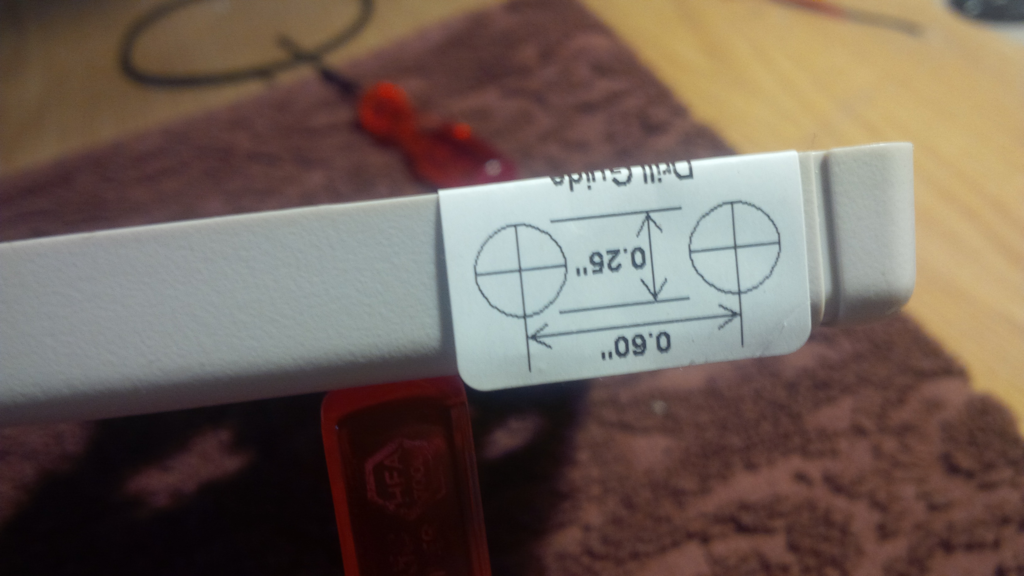
The module is delivered with a "drill guide" that you are supposed to glue on top of the case to drill holes. Unfortunately, the glue does not stick and whilst drilling the sticker is easily removed thereby leaving room for errors - and how many DMG original shells can you afford to mess up?
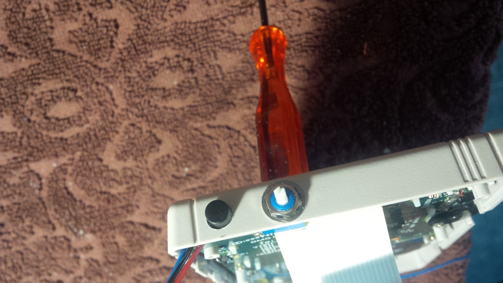
Potentiometer Cap Woes
The plastic cap that is supposed to cover the potentiometer is ludicrous:
- it is fastened to the potentiometer shaft via a single screw and bites into the plastic,
- it is way too large,
- it doesn't fit!!!! - the interior needs to be Dremeled a bit so it will cover the nut and the washer, otherwise it will scrape against the metal.
Just get a different one off E-Bay with matching dimensions. . .
Look at The Size of That Potentiometer
The potentiometer housing is almost a centimetre sized cube! Surely, there has got to be a smaller sized potentiometer providing the same values!
The worst part is that the module will make a tight fit and press against the DMG's top PCB - nasty!
No Documentation
None. Yep. None.
Drilling the Holes
The holes should be drilled on top of the Gameboy, opposite of the DMG's on-off switch.

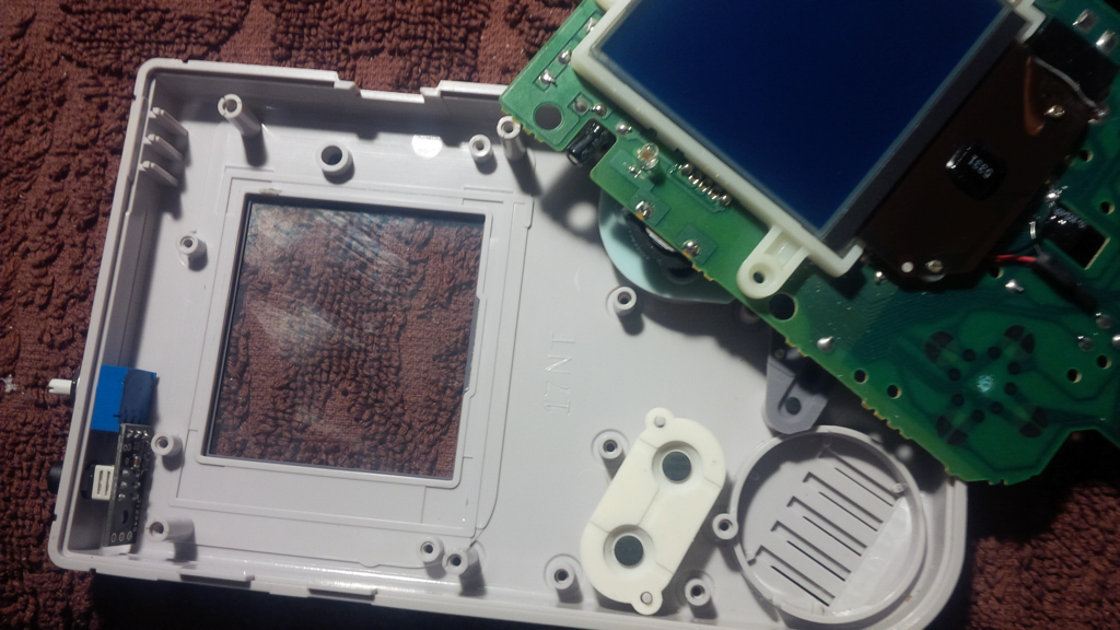
In the illustration note that the extreme right hole is to be placed between the standoffs - follow the red parallel lines as a guide. The module should not be too far to the centre either otherwise it will press against the ribbon cable (not a disastrous situation but still unpleasant).
Other guides suggest using a step-drill bit to drill the holes, by attaching some sticky tape marker to limit the depth.

However, the same effect can be achieved with some skillful manual routing using a Dremel rotary tool and a titanium boring head.

Soldering the Leads
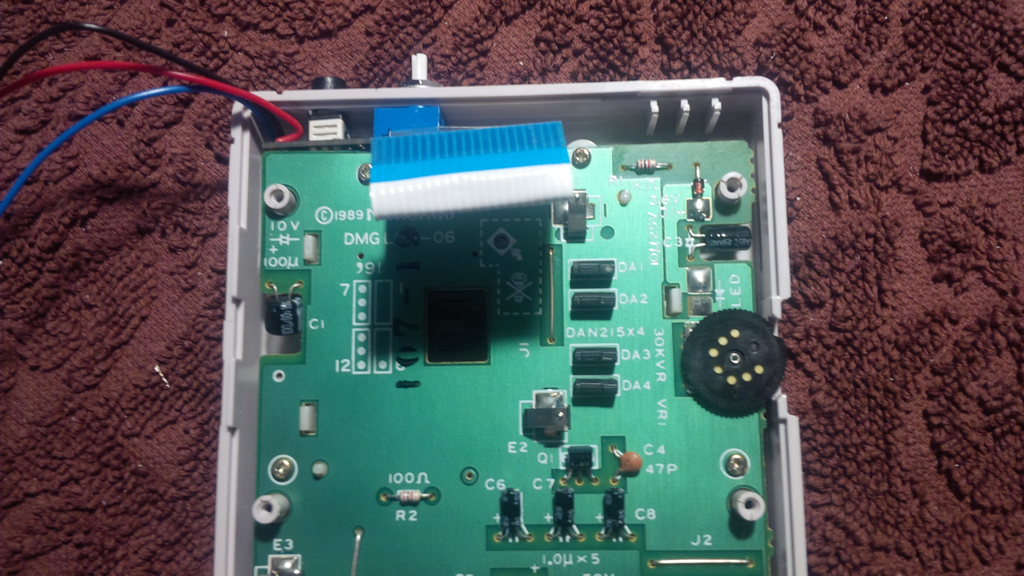
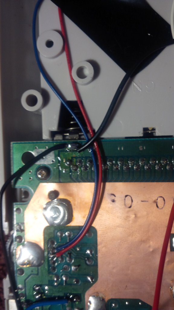
The module has three pad contacts next to the on-off switch:
VCC- should go to the positive pin of the battery compartment,GND- should go to the negative pin of the battery compartment,- center pad contact should go "somewhere" on the PCB as illustrated.
An overview image of the soldered leads would be the following:

along with the centre pad contact (blue wire):

Usage and Test Drive
It is wise to decide before turning on the Gameboy whether you will be using the module or not and turn the module on or off accordingly. Suddenly changing your mind and messing with the on-off switch whilst a game is running will crash the Gameboy depending how far the potentiometer is set from the original speed of  - most likely sudden large frequency changes are not tolerated.
The mod performs otherwise really well and is able to slow down or speed up games. Similarly, the mod is sometimes used by composers that use the Gameboy DMG as part of their DJing gear - speeding up or slowing down tracks!
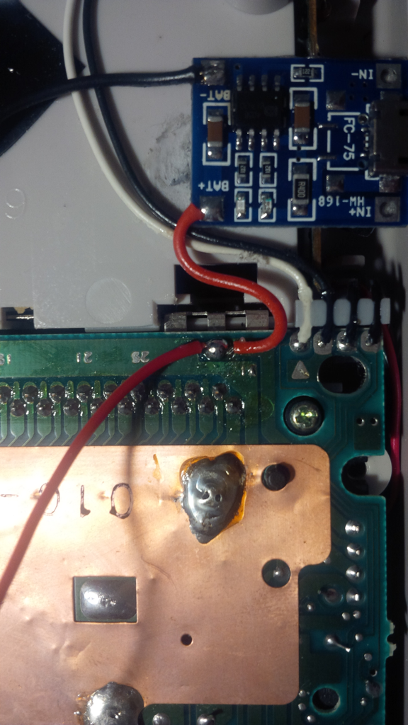
Gallery
You may notice a blue PCB on top of the battery compartment - it should not be there and it is a remnant of the usb charger mod.