Table of Contents
About
The BlizzardPPC has a thick sheet made out of aluminium that is held down by clips and is supposed to be the heatsink for the PPC. Unfortunately, the heatsink barely touches the PPC and can also be displaced easily mechanically just by twisting, such that thermal paste is used for a better contact.
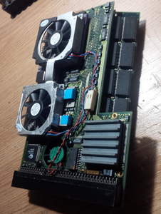
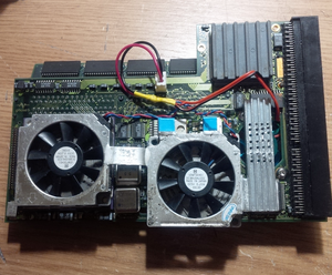
The following tutorial shows a simple design using two  fans out of aluminium that act both as a passive and active heatsink.
Materials
- two
 ,
,  fans with an aluminium casing,
 - thermal tape,
- aluminium sheets,
- dremel,
- artic alumina adhesive - the two-part bonding substance.
Design Cristicism of the Stock Blizzard PPC Heatsink
The stock heatsink of the Blizzard PPC is a very bad design by modern standards and it may just as well have a negative effect on the Blizzard PPC if left unreplaced. It can be observed that over the years Amiga software, even for a dead platform, has been evolving such that the stock heatsink may, at some time, have been a fair solution however even mediocre modern-day solutions prove to be a better solution for cooling both processors. Perhaps, some of the reasons why the heatsink may be a bad design are the following:
- the heatsink is closed and does not let air circulate - an enclosed space is created around the PPC that is supposed to be venitlated by a small fan but with very few apertures to let the heat escape.
- the heatsink is oversized, in a bad way, since it encloses a CPLD chip, two power transistors and several other components with which the heatsink does not even make contact; instead, the components are to be found underneath the heatsink, releasing heat, only for the heat to be mixed up with the heat from the PPC.
- the heatsink seems to be made out of pure aluminium without any fins to dissipate the heat.
- the heatsink is not properly clamped down by the clips such that any touch on the heatsink simply dislocates it and lets it wobble around.
- even if thermal paste is added between the PPC and the heatsink, the paste will end up smudging allover.
- the clips that (are supposed to, but do not properly) keep the heatsink in place are secured on the other side of the board and protude enough such that exclusive low-profile RAM sticks may be used (without applying any torque to the holding clips of the RAM sockets).
- the fastening system, namely, the clips are very easy to accidentally dislodge.
- although tangential, the 060 does not have any stock cooling (and the 060 is commonly overclocked from
 to
to  ).
).
The stock heatsink should be removed from the BlizzardPPC along with the aluminium clips and held in storage.
Design
The 060 tends to not heat up as much as the PPC such that the thermal area can be shared by both the 060 and the PPC. Two  fans are placed down upon both the 060 and the PPC and then joined together using an improvised heatpipe made by cutting some spare aluminium sheet. The fans are secured using thermal tape only and are not fastened permanently to the chips. The improvised heatpipe is joined to both fans by using some adhesive thermal compound (ie: Artic Silver Alumina Adhesive). Both fans are then coupled to the fan pins of the Blizzard PPC.
Two L-shaped struts are cut from the spare aluminium sheet in order to be placed onto the two power transistors just above the PPC chip. The L-shaped struts are fastened to the fan over the PPC by using adhesive thermal compound but the struts are not permanently attached to the transistors. Instead, mechanical force is used to hold the assembly in place and, for a better thermal surface, some thermal tape is applied over te L-shaped strut and the transistors.
The small stock fan can either be removed or kept as it is - perhaps, better air circulation is achieved if the fan is not removed. In further developments, the fan has been replaced with a Ya-racer fan with a high rotation speed. Furthermore, a strut has been added on top of the chip next to the PPC and extended over the hole in the PCB. Then, a heatsink has been added with holes drilled in order to better dissipate heat, as well as increase the overall thermal mass of the improvised heatsink. The fan connector has been replaced with a more sturdy variant that provides better locking for the leads that provide power to the fans.
A final addition consists in a few chipset coolers for the RAM chips that have been added to better dissipate heat.
Removal
Removing the improvised heatsink would imply using a cutter or slim blade to detach the fans from the CPUs since they are just held down using thermal tape. Simiarly, the thermal tape around the struts and the transistors can just be removed.
Unfortunately, removing the assembly would mean that new thermal tape would have to be applied if the improvised heatsink would have to be used again. On the other hand, removing the heatsink would only really be relevant for a CPU upgrade, otherwise, there is not much point in removing.
Gallery
For the contact, copyright, license, warranty and privacy terms for the usage of this website please see the contact, license, privacy, copyright.


