Table of Contents
About
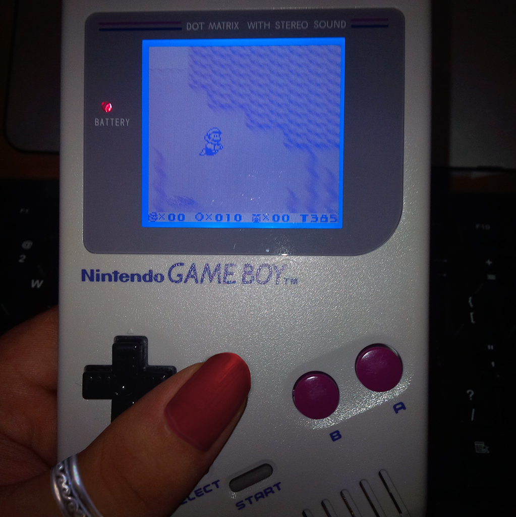
The Gameboy DMG takes 4xAA batteries to power up. Furthermore, the DMG batteries cannot be charged even if rechargeable AA batteries are installed. The only way to ensure that you have sufficient power for your gaming session is to lug around reserve batteries and, given the size, that is a lot of weight to carry around for a "pocket console".
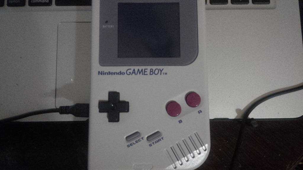
Unfortunately, the DMG appeared well before the USB era but with some skills and cheap materials the DMG can be modded to install a mini-USB charger PCB such that the DMG can be charged from any USB power source (including laptops, or others).
Requirements
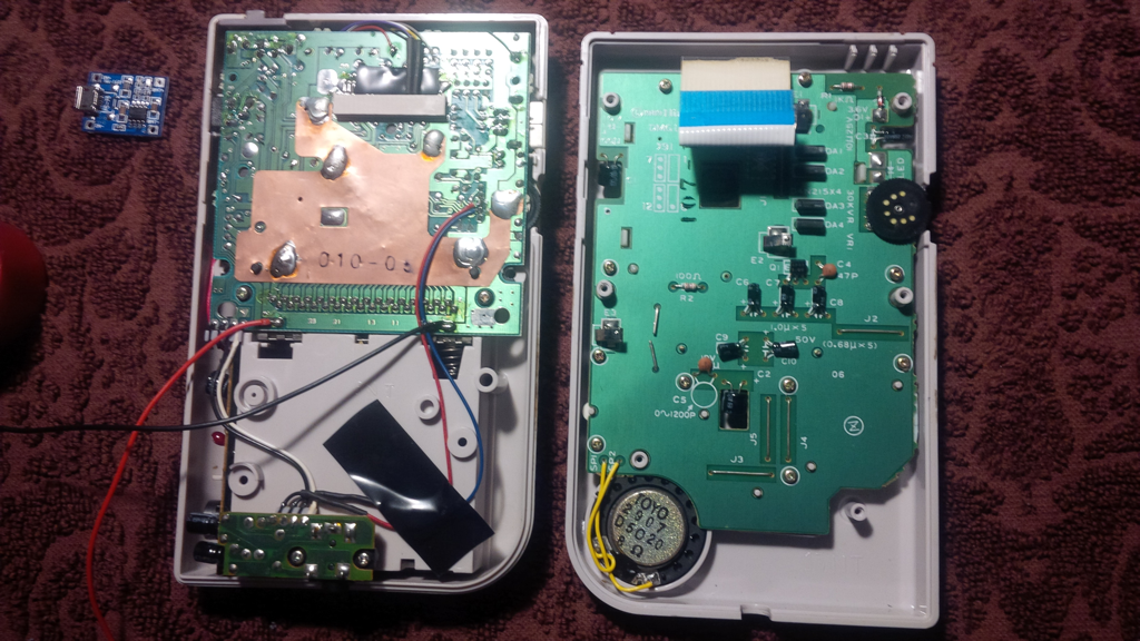
- TP4056 5V Micro USB 1A Lithium Battery Charging Board Charger Module - this low-cost module provides 5V output with up to 1A charging current and is most suitable given its small dimensions (smaller than a 20p coin). As mentioned, the DMG takes 4xAA batteries and an AA battery outputs from
 to
to  . The
. The TP4056can be bought on E-Bay from China for a meagre USD1!

- Two wires to connect to the cumulative anode and cathode of the 4xAA batteries - the gauge is not too important but keeping the wires small would help having more room inside the DMG.
- Soldering equipment - goes without saying, nothing fancy is needed though because the only soldering to be done will be to attach the wires from the
TP4056to the battery compartment.
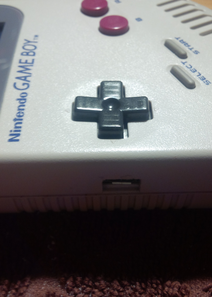
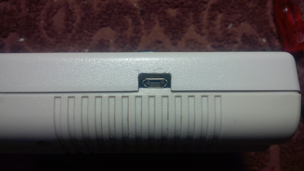
- A Dremel, chisel and sandpaper - the most difficult part of this mod is getting the etch right through which the mini-USB port will protrude. Given some skill, the etching can be made really tidy so it does not look too homebrew.
- Two Gameboy DMG screwdrivers - one could wing this requirement but the DMG screw holes run very deep such that a hobbyist screwdriver may not reach and may not grip the heads. The screwdrivers can be obtained from Handheldlegend for USD2.5 or even cheaper via Chinese sellers on E-Bay.

- 3M VHB double sided sticky foam sheet - used to fasten down the
TP4056onto the plastic. The 3M double sided sticky foam sheet is extremely strong and provides a tidier solution to using a plastic gun.

Opening the DMG
The DMG can be opened by removing 4 screws on the outer shell and then 2 more screws on the inside of the battery compartment. Once open, the flat LCD ribbon cable will have to be carefully removed by pulling it out of the socket - a tricky experience but not that difficult to do with sufficient time and care.
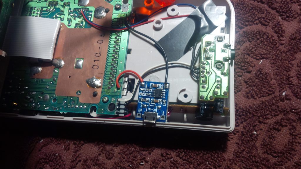
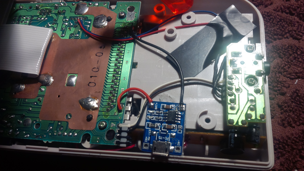
Placing the USB Charger Module
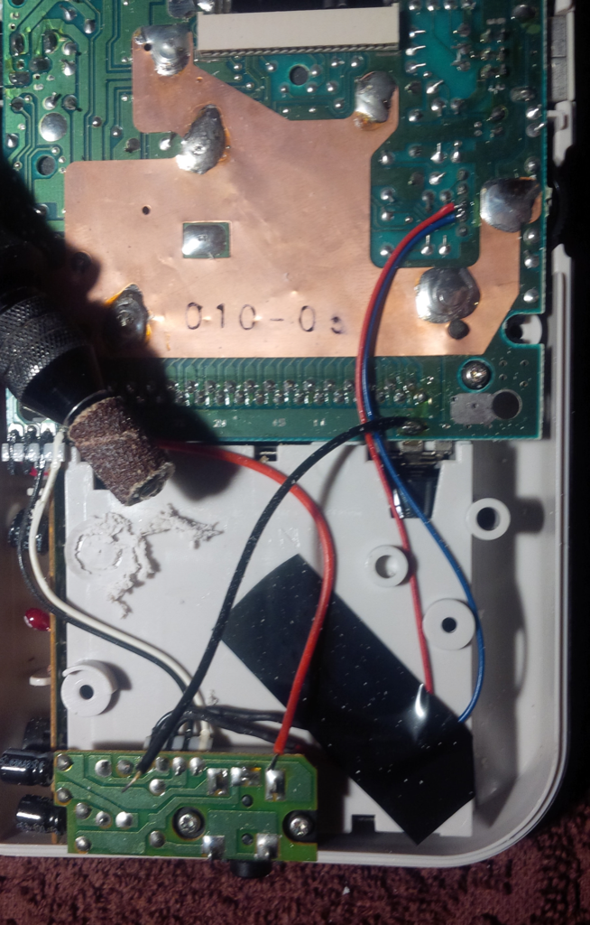
The best spot to place the TP4056 micro-USB charger PCB is right next to the audio controller board. There will be a plastic cap that should first be ground down to the shell using the Dremel. Slow circular movements will easily grind down the plastic cap and remove the excess plastic. The plastic protrusion looks like a screw slot but it is not used in any way and is probably just a production feature that ultimately served no purpose.
With the excess plastic trimmed off, the TP4056 is fastened down onto the battery case with some 3M VHB double-sided sticky foam tape. Most Gameboy mods involve securing extra PCBs with plastic hot glue but the plastic glue tends to wear off in time and it is a very messy business. The VHB double sided foam from 3M is a neater alternative.
Lastly, solder the leads from the TP4056 pads to the battery holder pins attached to the DMG PCB.
Verifying Charging Load
Testing with a multimeter shows that the TP4056 is admirably spot on with voltage that peaks at precisely  ! Furthermore, the
 TP4056 has two bright LEDs which will:
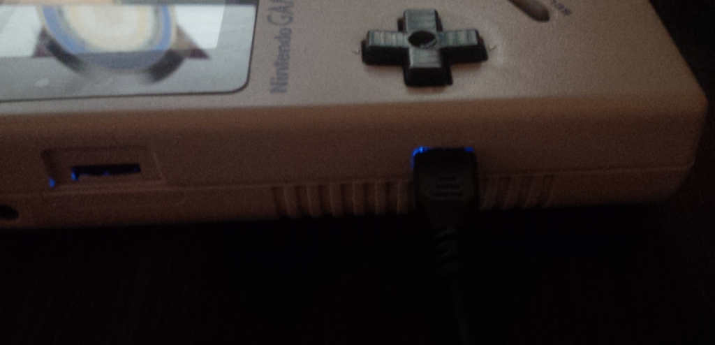
- flash blue when the batteries are charging.
- intermittently flash red in case the batteries are not charging.
The latter behaviour can tested simply by removing one of the 4xAA batteries, thereby breaking the circuit.
Further Developments
A small piece of optic fibre can be used to route the LEDs to the outer shell through a drilled aperture. In order to do this, you would drill a small hole next to the mini-USB etching and glue the optic fibre on top of the LEDs. Some black liquid tape can then be used to seal the LEDs and ensure optimum flow through the optic fibre cable to the aperture thereby creating an outer shell indicator.
Gallery