Table of Contents
About
One of the more difficult Amiga 1200 modifications to perform is to get a FastATA MK-III extension to fit alongside an Indivision MK-II Cr2 graphics card inside the traditional Amiga wedge case. The problem stems from the fact that the FastATA is not a compact device: it is quite large, it takes ROMs on top and needs a lot of room; similarly, the Indivision, albeit flat, is relatively long and fits on top of Alice but extends to the RAM chips on the Amiga 1200 board.
Elbox, the producer of FastATA, officially instructs you to mount the FastATA on top of the ROM sockets - yet, if you also have an Indivision, the FastATA will not sink into the ROM sockets and even if you push hard enough, it will just bend on top of the Indivision - which is both unsafe from a mechanical point of view, as well as electric since the FastATA circuitry could short the Indivision circuitry.
This is a proposed modification to the FastATA component that, albeit laborious, it makes the FastATA work together fine with the Invidision, as well as leaving plenty of wiggle-room for add-on fans and allowing you to keep the original wedge-shaped case of the Amiga 1200.
Alternative Modifications
One of the most common alternative modifications that have been documented consists in extending the FastATA ROM socket pins such that they will reach the ROM sockets on the Amiga motherboard and let you mount the FastATA on top of the Indivision. Unfortunately, this is not an acceptable solution since it will make the FastATA hit the keyboard that fits on top which leads to having to bend the ROM socket pins and slide the FastATA at an angle.
Requirements
Here is a full list of requirements along with their purpose. We list the components that were used or were useful and those that were obtained from "flea markets" such as Ebay. There may be better alternatives if you have the right access to industrial apparel:
| Requirement | Usage | Image |
|---|---|---|
| Spare ROM chips. | Having a few ROM chips to spare is a good idea in case you damage a ROM. Fortunately, damaging a ROM chip would amount to about an USD8 penalty, whilst damaging the Amiga board or the FastATA itself can reach up well in the 100s of USDs. |  |
| A good fresh nipper. | The nipper will be used to trim down excessive pin lengths on the bottom of the FastATA. The word "fresh" is important since we want a clean cut and do not want a used nipper that will either not trim to the lowest height possible, or will just bend the pins instead of cutting them. |  |
| Single-sided adhesive isolator (we used cork) | This isolator is glued on the bottom of the FastATA after the pins have been severed in order to isolate the circuitry. A cork single-sided isolator is pretty good since cork is a non-conductive material, easy to remove and soft to the touch. Rubber is also a good one. |  |
| 40-Way Flat Ribbon IDC Cable | The ribbon IDC cable will be used to form an extension cable for the ROM sockets that will allow you to relocate the FastATA to some other area inside the case with more free space. Be generous when you buy this because you may need a few tries - 2 meters should be good enough and give you about 4 tries in case something goes wrong. |  |
| 2.54mm x 15.24mm Pitch 40 Pin Male Header IDC Cable Transition Connector | These connectors will be used together with the aforementioned ribbon cable to create the extension cable for the ROMs. Be even more generous than with the ribbon cable on this one: Buy 10 or even 20, just to make sure you have enough tries. They are very cheap per piece and sellers will mostly sell these in packs of 5 or 10 anyway. | |
| 40-Way DIL IC Round Pin Sockets | These will be used to create a makeshift socket on the bottom of the FastATA since the cable will go on top and the ROMs will go on the bottom and there is only one socket on top for the ROMs. Again, be generous on how many you buy - they are usually very poor quality (the plastic) and snap easily when applying pressure. This component is the one you're most likely to mess up a few times. |  |
| Ohm-meter, continuity tester or multimeter | This is the most vital thing to have. Everything you will be doing will be so small and the components will be so frail that you will not be able to rely on your senses to tell you that you have proper contacts. Do not even start without one of these or down the line you will think and notice that everything looks just fine and then when you turn on the power, due to some hairline connection, a short it made and you melt either your ROM chips, the motherboard, the FastATA and others. |  |
| Silver conductive glue syringe | The mechanical connection of the suggested assembly should be enough but if you want a touch of "bling", the silver conductive glue can be applied to the joints to form a bond between the metals - a bond that can be easily removed in case you want at some later time to change the kickstart ROMs. Very optional. |  |
There will be no soldering required for the project. There is a step where you can - and probably should if you are alright about having to desolder in order to change ROM chips. If you want some middle-ground and "just-to-be-certain" solution, you can also purchase some silver conductive glue - they come in syringes. "Conductive glue" is pretty bad, it leaks, it's easy to mess up because the glue is mostly runnier than you'd have hoped and, in the end, you should not rely on it for a good connection. Nevertheless, it does harden and helps just a bit to hold the mechanical assembly in-place for minor vibrations such as the one exerted onto the FastATA by, say, fans that you may have in your Amiga case. The solution presented in this document is only mechanical but, if you want to add "a cherry on top", get some silver glue with a very fine-tip syringe.
Methodology
We are going to create an 40-way IDC cable with sockets on both sides in order to extend the ROM signal from the Amiga 1200 motherboard to the FastATA board. The FastATA board will thus have the socket of the extender cable on top. On the bottom of the FastATA board, we are going to create a makeshift socket and fit the Amiga kickstart ROMs on the bottom.
Creating the Cable
Creating the cable consists in trimming the ribbon cable to some desired length, fitting the ribbon cable inside the ROM header connectors and then applying pressure equally onto the surface of the ROM header connectors such that the ROM header teeth sink into the cable and make a connection.
  +------------------------------------------+
  | ^                                        |
  | | up         U6A cable head              |
  |               (lower ROM)                |
  |                                          |
  +-++++++++++++++++++++++++++++++++++++++++-+
    ||||||||||||||||||||||||||||||||||||||||
    ||||||||||||||||||||||||||||||||||||||||
    ||||||||||||||||||||||||||||||||||||||||
    ||||||||||||||||||||||||||||||||||||||||
    ........................................
    ........................................
    ........................................
    ||||||||||||||||||||||||||||||||||||||||
    ||||||||||||||||||||||||||||||||||||||||
    ||||||||||||||||||||||||||||||||||||||||
    ||||||||||||||||||||||||||||||||||||||||
  +-++++++++++++++++++++++++++++++++++++++++-+
  |                                          |
  |              U6A cable head              |
  | | up          (lower ROM)                |
  | v                                        |
  +------------------------------------------+
The illustrated "up arrow" hints to the fact that the connectors should be back-to-back or facing in opposite directions. We want to do this for the lower ROM because we want to be able to rotate the connector and plug them facing each other - otherwise, the cable would not allow us to plug them into the socket on top of each other due to the lack of space.

Notice on the second diagram how the bottom header cable U6A has the two triangles opposed to each other if you were to straighten out the cable. Also notice that the upper U6B header has the triangles following each other in the same direction.
To create the cable you will need to cut the ribbon cable straight on both ends, slide the ribbon cable into the header and apply pressure. You can do this with a few slices of rubber (to not damage the plastic) and a pair of pliers - on the other hand, if you want to be pedantic, you can invest in an IDC / IC head crimper.

The IDC / IC crimping tool will allow you to do this in a jiffy, not risk damaging your headers and the result will look clean.
Once your ribbon cable with headers is complete, the last step to work on is to splice the cables of the ribbon cable in order to be able to pull the individual wires together and make the cables more flexible and gain more space.
Do not take the scissors literally, they are symbolic and a very bad idea if you use scissors. One solution that works is to splice the individual wires by using a dull bottle-cap opener and lightly apply pressure, scratch the thin division between two wires till you get an aperture and then finally and very gently pull on the cables. It is perhaps one of the more annoying tasks of this project since the individual wires of the ribbon cable are very frail and one bad move and you cut into the wire. In case that happens, you have to solder the cables together and use some heat-shrink isolator to restore the connection. Splicing also can only take place after you have mounted the cable headers - otherwise you will not be able to crimp the IDC headers onto the ribbon cable.
After a lot of hassle you should obtain two separate cables with headers for the bottom and top ROM sockets. If you impulse is to optimise the cables with some cable porn - do not go that route just now. The idea is that when the individual wires off the ROM sockets are loose, you can bend them easily and they are not rigid such that you can adjust them around the keyboard that has to go on top, or move them around inside the case to get to an optimal position.
Preparing the FastATA Board
The underside of the FastATA adaptor has some protruding pins that should be clipped and trimmed down such that we can cover them with an isolator. The FastATA adaptor pins are abnormally large on the bottom part and with a good fresh nipper they have to be cut down as close as possible to the board.

After the pins are clear, you can trim and apply a sheet of adhesive cork on top of the circuitry. This will take care that the FastATA circuitry does not short if it comes in contact with other circuitry.
Grafting ROM Sockets onto the FastATA Bottom Pins
Now a makeshift socket will have to be created and placed over the bottom pins of the FastATA connector such that we can connect the kickstart directly to the FastATA adapter. In order to do that, we take the 40-Way DIL IC Round Pin Sockets and cut the pins just enough so we expose the cylindrical aperture and obtain a through-hole.

This through-hole will envelop both the ROM pin and the FastATA pin and will be held together mechanically - although, if you really want, you can use the silver contact glue to ensure some resistance to vibrations. Nevertheless, you should consider not soldering the assembly because, although unlikely, you may want to change the ROM chips later.
The next step is to take your kickstart ROMs and reverse their pins all the way around. This task is very sensitive depending on the ROMs you have. AmigaKit ROMs seem to be produced with some extremely brittle aluminium pins that will break off way before you manage to turn the pins to 180 degrees.

Do not even attempt this if you have AmigaKit ROMs. The "original ROMs" work better - or any other type of ROMs that you can find on the flea markets seem to have more sturdy pins.
You will have to take each ROM chip and bend the pins around. Your best tools, by far, are your soft fingers - a long, blunt, thin and rigid widget (something like a credit card, but thinner) will also help you bend the pins around. Try to make a gentle but decisive single move when you bend the pins and make as few adjustments as possible to each individual pin.

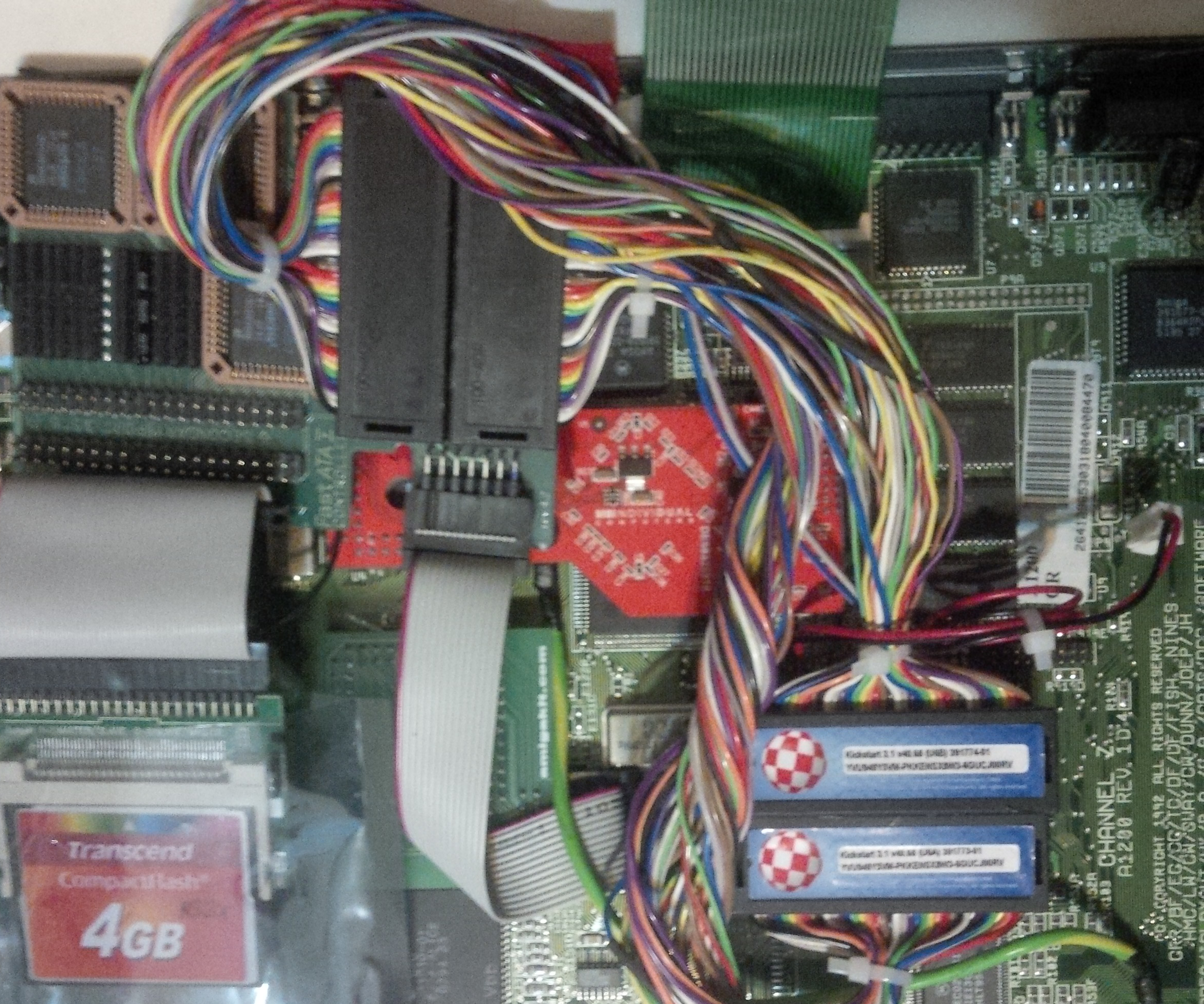
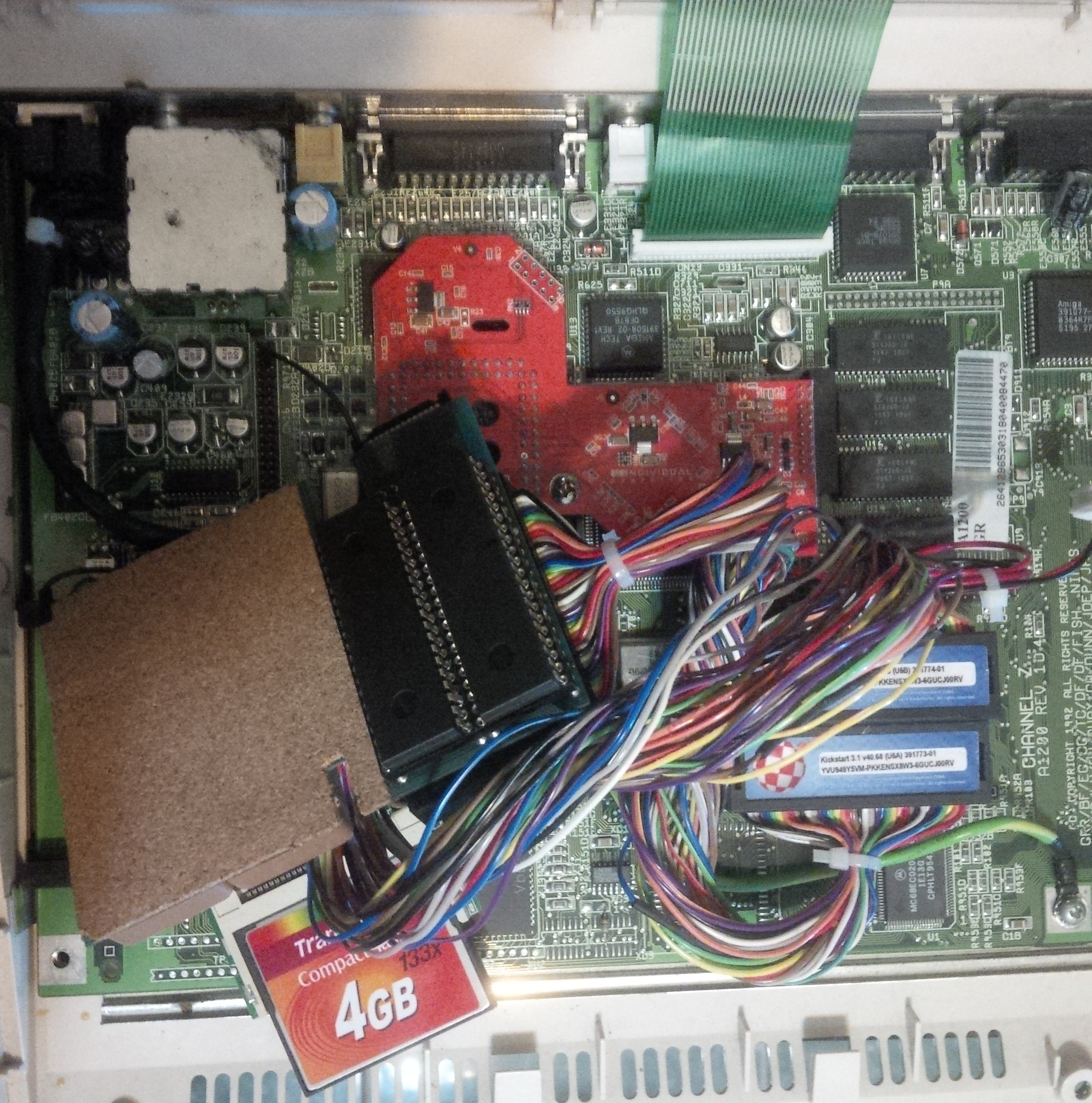
The final assembly will have the ROM extension cable fitted into the stock ROM sockets and the back / underside of the FastATA board will have the makeshift socket fitted. The kickstart ROMs will be fitted into the makeshift socket on the underside of the board.

Lastly, the kickstart ROM orientation on the underside of the FastATA board has to be precise. The pins were bent on the kickstart ROM chips in order to fit them in the same order that matches the Ribbon cable.

If you consult the FastATA manual, you will notice that the pin orientation has to be respected: it's quite trivial, the top-most pin on the top U6B Amiga motherboard ROM socket has to connect to the top-most pin on the top side of the FastATA board. Since we have the pins rotated around, the label on the ROM has to face down onto the FastATA board and the label or text has to point upward.
Applying Silver Conductive Glue to the Bonds
Most of the mechanical strain will be on the extremities of the ROM sockets. The mechanical strain is very minor and mostly due to tertiary vibrations such as the ones exerted by fans. hard-drives or other devices with moving mechanical parts - throwing your Amiga on the floor is not implied! Silver conductive glue can be applied from a syringe, between the cylinder and the protruding pins of the FastATA board in order to strengthen the bond.
The application of silver conductive glue can get messy real quick and it is suggested that you hunt down some silver conductive glue that is not runny - ideally, this should be replaced by the more expensive epoxy (or rather just solder them. . . ) but we want a weak bond so we can remove the ROMs at a later time if so desired.
There is a high risk of creating a silver lead between two pins of the kickstart which will lead to damage! It takes a vulture's eyes and a surgeon's hands to make this work. . . Best leave it alone and make sure to measure conductivity to be certain you have not created a short that should not be there.
Fitting the Hard-Drive or Compact-Flash Card
Clear rule: the red-colored wire of the ribbon cable that connects to your hard-drive should go to the pin marked as number 1 on the FastATA IDE connector.
In other words, the red-colored wire of the IDE ribbon cable indicates pin 1. Compared to the Amiga motherboard, the FastATA board is not that lenient about inserting IDE devices the wrong way. To be sure, always check, and always search for more information.
If your hard-drive does not boot, or boots into AmigaDOS, then your assembly was successful! FastATA may require you to reformat your hard-drive. However, if the assembly failed, then nothing will work and you will know early on, way before reaching the AmigaDOS window or Workbench.
In case you use a compact-flash device instead of a hard-drive, a neat isolation solution is to take one of those "static electricity-proof" bags that are used to ship electronics in and cut a sheath, insert the CF reader inside and use some sticky tape to make sure the CF reader does not fall out (see gallery). This will ensure that the CF reader and cards will not short some random circuitry as it rests back onto the Amiga motherboard.
Measurements
You get one shot at this assembly: it either boots fine into kickstart or even directly into your Workbench, or the ROM pins are poorly connected, in which case something will fry and your Amiga might never boot again. It is thus imperative that the conductivity is measured for:
- the kickstart ROM pins, once the ROM is attached to the assembly.
- the modified ROM "ribbon" cable.
- the kickstart ROM pins on the back of the FastATA board should lead straight-through to the stock ROM socket of the FastATA board.
Once the ROMs are fitted onto the makeshift ROM sockets and pressed together onto the FastATA pins, the ROM itself can be measured for conductivity. Each two pins of the kickstart ROM, measured together, should not show any conductivity between them - except for a particular case of two pins somewhere at the middle of the ROM chip that should indicate a small resistance.

The "ribbon" cable (now just a tuft of individual wires) should connect pin-to-pin with the ROMs on the underside of the FastATA board. It is trivial, yet it can be tricky due to the rotation of the cable and the bending of the ROM pins. If you have any spare ROMs, you can perhaps place them over as they should be placed without the modification and mentally visualise which pin goes to which socket aperture and then measure if you have the proper continuity.
Also, a trivial measurement would be to check that there is continuity between the individual kickstart ROMs pins mounted on the underside of the FastATA and the small pin slots of the stock kickstart socket on the top side of the FastATA card.
Booting and Testing
It is a good idea to isolate the kickstart ROM assembly on the underside of the FastATA with some sticky tape - it will be removed after that but it is a good idea since you may not want to go ahead and mount the FastATA into its final position.
Here is the pre-flight check:
- The ROMs on the FastATA should, if the procedure is applied correctly, not jerk around even if you wave the FastATA in the air like a featherduster
 In case the ROMs bounce around, you should check the assembly again and remember to add some silver conductive glue if you really want to be sure. You can at any time ensure connectivity by soldering - yet, you will have to desolder in case you want to change the ROMs. However, the mechanical straing should be enough to hold the assembly fast.
 - Make sure that the cables, especially headers are well-seated in the Amiga motherboard and in the FastATA board. Always apply gentle but steady pressure when inserting ROM pins into sockets. Make sure that the force exerted as you insert the ROMs is perpendicular to the surface of the ROM. Mess around as little as possible with the extremities of the ROM - even if you will find that those pins will seem more cooperative, you risk bending the pins.
- Measure everything like you are suffering from amnesia - you have some doubt about the assembly? Jolly well, measure it again! All the pins, the cable, again! Obsessively!
- When you boot-up the Amiga, the very first indicator that the assembly succeeded, should be either the Indivision banner pop-up on your TV or monitor, and if you have an accelerator, then any banners from the accelerator should act normal (ie: Blizzard accelerator blue lines). Instead, if at any point you see "weird" (never noticed) lines on your screen, horizontal white lines, graphics corruption, abnormal fluttering of the Amiga indicator LEDs, weird sounds or no floppy-drive sounds then act immediately and shut down the Amiga! At best, you keep your thumb on the switch in order to be able to react immediately. Nevertheless, keep in mind that the FastATA board will make your Amiga take longer to boot into your Workbench so do not panic if it does not boot as fast as you would expect it to. There is indeed a phsychological cringe barrier between turning on the Amiga and waiting for either the AmigaDOS prompt or noticing the hard-drive LED light up intermittently, indicating the OS loading.
Final Thoughts
Although the purpose of this modification is to allow you to still use the original Amiga wedge case, it is also a good modification to use in a towerized Amiga due to the amount of space and flexibility it can grant you. Similarly, the FastATA is originally delivered with some straps and the only mechanical connection between the FastATA and the Amiga motherboard is through the ROM pins and the additional "shaky" straps. What is worse is that the FastATA would be resting on top of the Indivision and heat may build up given the lack of space for ventilation.
One of the side-features of the modification is that it allows you easy access to the motherboard ROM sockets such that you can pull lines (for instance, when using a clockport multiplier). Even with the original modification with bent socket pins, you would not be able to run a clockport multiplier due to the lack of space between the keyboard and the motherboard.
A different approach would be to use hot air and solder the kickstart ROMs onto the FastATA board. The upside would be that you will have a very solid electric connection but the downside would be two-fold: you would have to desolder to change the ROMs and you really risk damaging the FastATA since the stock socket is made of plastic and very close to the pins onto which you'd direct the hot air nozzle. It also appears that kickstart ROMs are more vulnerable to heat than other components. It is a very difficult hot air solder and a mechanical solution was preferred for this modification.
Gallery
Gallery Errata
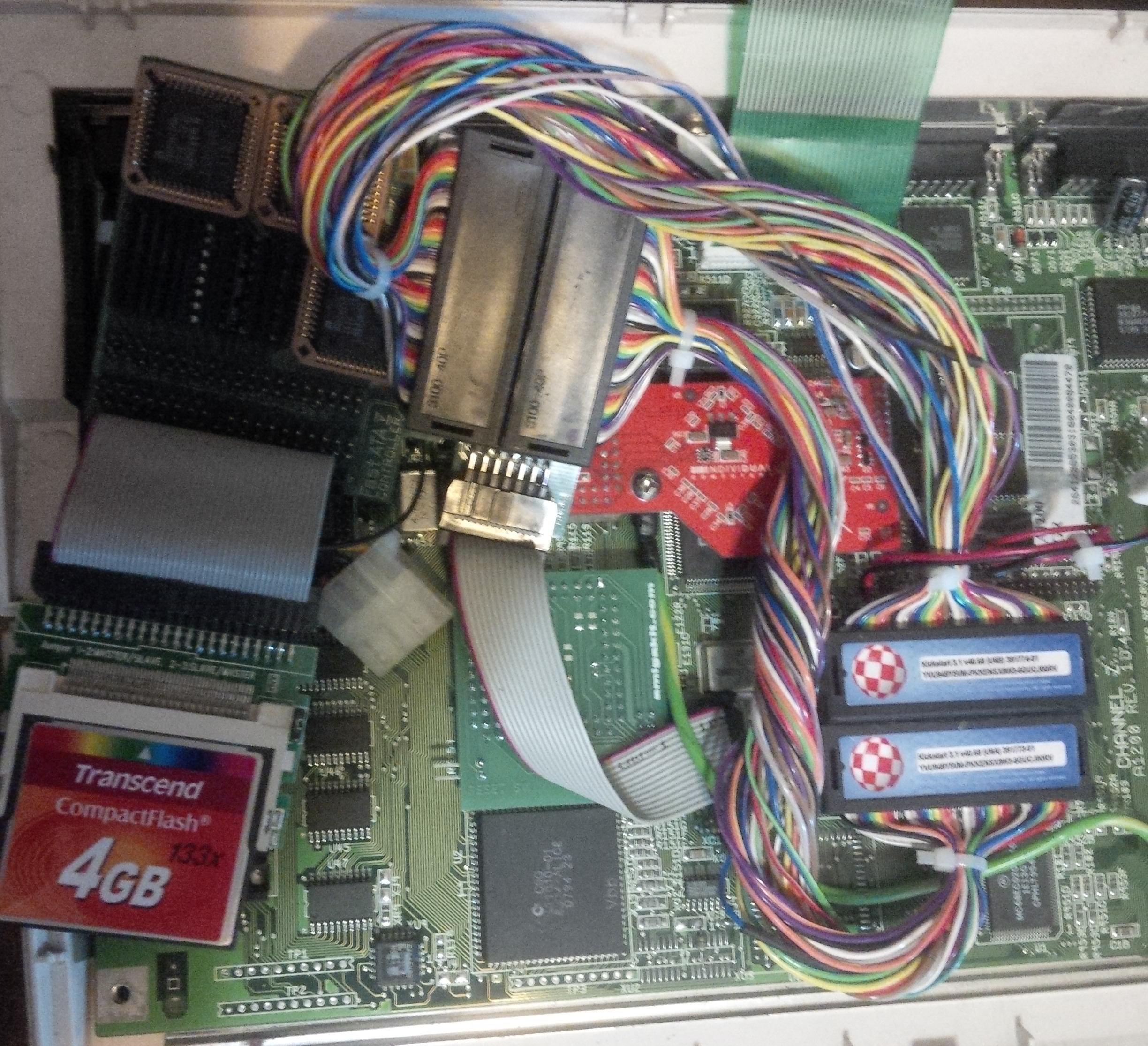
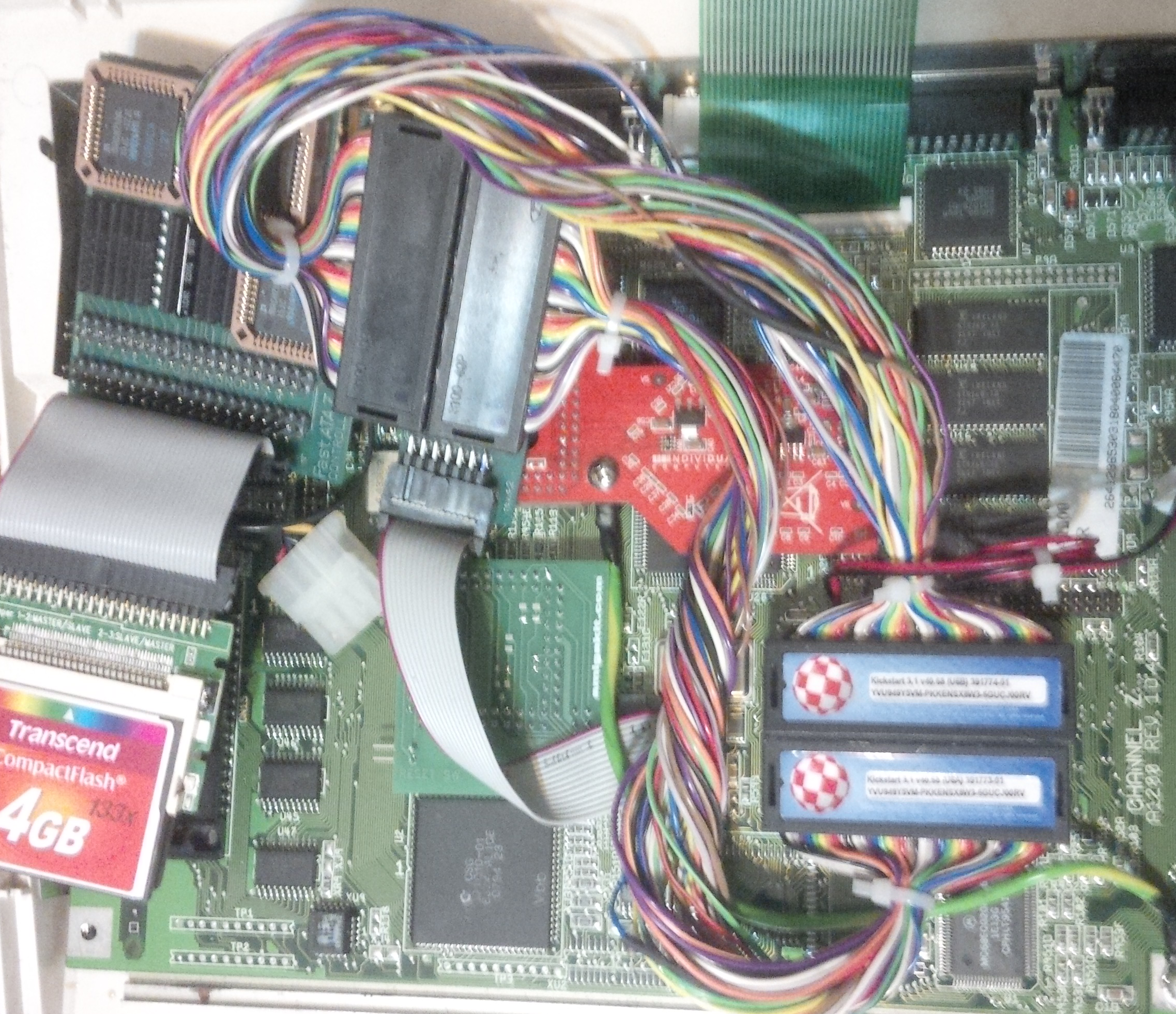
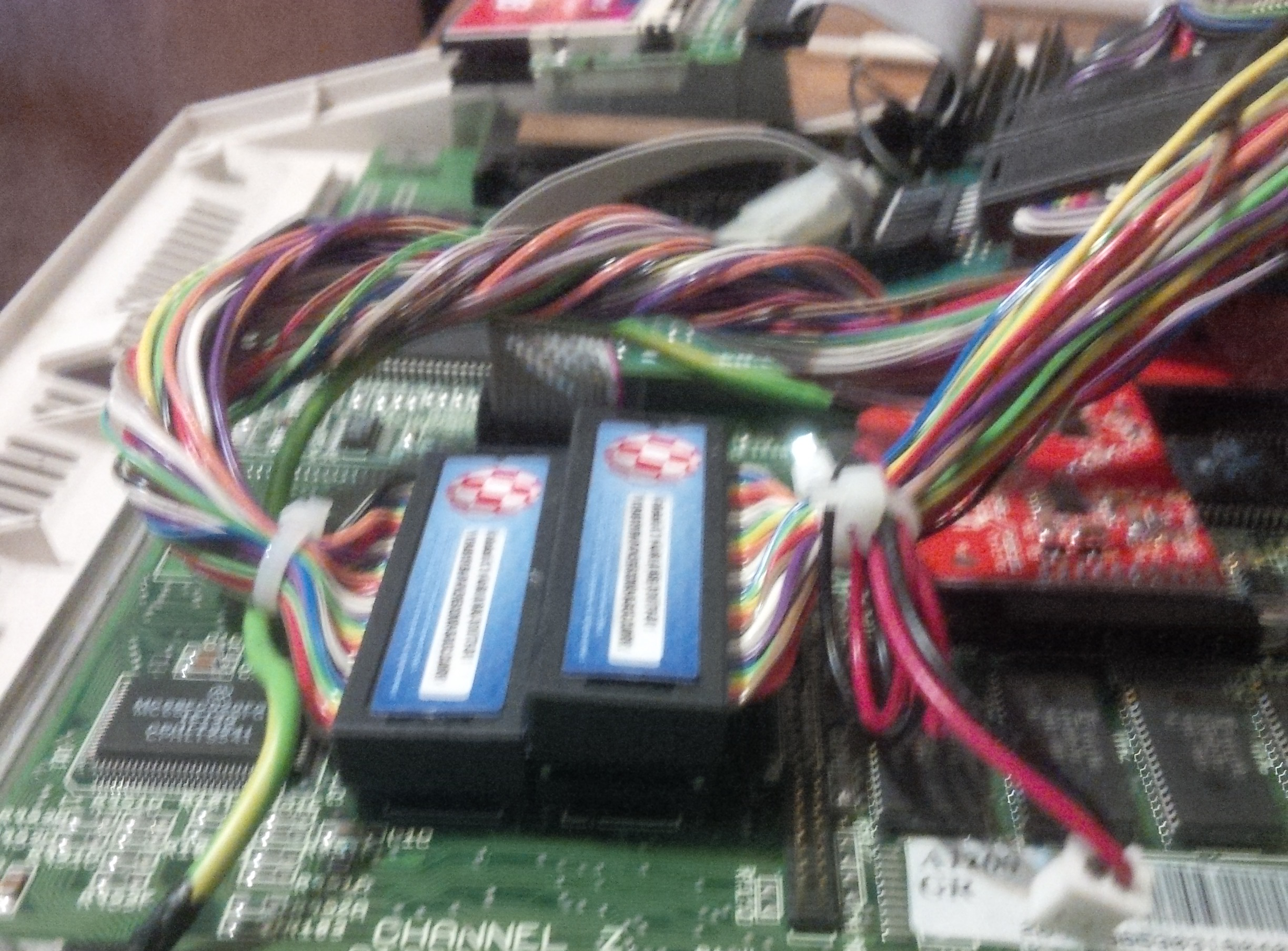
- One motherboard IDC header connector seems to be placed higher than the other - this is due to an additional and unrelated mod that requires some pins to be connected. It bears no relevance to the modification described on this page.
- There are two stickers on the motherboard IDC header connector that would indicate that the ROMs used were the type that were explicitly recommended against on this page due to their pins breaking off easily… That's right, in fact, the labels are there due to a previous attempt to bend the pins and breaking them off, so the labels were salvaged instead and stuck to the IDC headers to make them pretty. The kickstart ROMs attached to the back of the FastATA are of a different make.
Finishing Touches
- The IDC / IC headers allow for stickers to be placed - finding or printing some colourful and catchy ROM stickers could make both ends of the IDC / IC headers cute.
- Some cable-management could be applied for the wires - however, the flexibility of the wires should be preserved or else the bottom of the keyboard will press against the cable coming out of the lower U6A ROM header and prevent the case from closing.
- A good position with room would be to place the FastATA on top of the RF shield and above the Indivision. It fits nicely and can be attached through various means (double-sided sticky-foam).